
Set of Components Able to Be Coupled Together

a technology of components and components, applied in the direction of couplings, rod connections, dismountable cabinets, etc., can solve the problems of deterioration of connection, rapid wear and tear of connection methods involving frictional fit or deformation of components, loose and unstable frame structures,

Inactive Publication Date: 2010-01-21
KEYVANLOO AYDIN +2
View PDF16 Cites 14 Cited by
  • Summary
  • Abstract
  • Description
  • Claims
  • Application Information

AI Technical Summary

Benefits of technology

[0021]The first component advantageously further includes a locating device provided on each stub portion which assists in locating the stub portions in the respective socket portions of the second components. The locating device is preferably spring-loaded and once turned to engage, creates a positive stop at the locked position. The locating device preferably includes a set of locating teeth formed on an interior surface thereof that complement a set of locating teeth formed on each stub portion. The complementary sets of locating teeth advantageously permit rotation of the locating device radially about the stub portion in 45° increments. The locating device is preferably shaped such that once the respective stub portion and locating device is inserted into a socket portion and rotated through 45° to engage the teeth of the stub portion and the teeth of the socket portion, the locating device is prevented from turning relative to the second component.

Problems solved by technology

Connecting methods involving frictional fit or deformation of components have been observed to be subject to rapid wear and tear, particularly in commercial environments where shop display structures are frequently dismantled and reassembled.
Wear and tear on components quickly leads to a deterioration of the connection and leads to loose and unstable frame structures.

Method used


Image

  • Set of Components Able to Be Coupled Together
  • Set of Components Able to Be Coupled Together
  • Set of Components Able to Be Coupled Together

Examples


Embodiment Construction

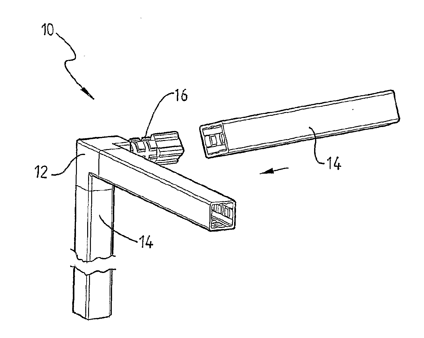
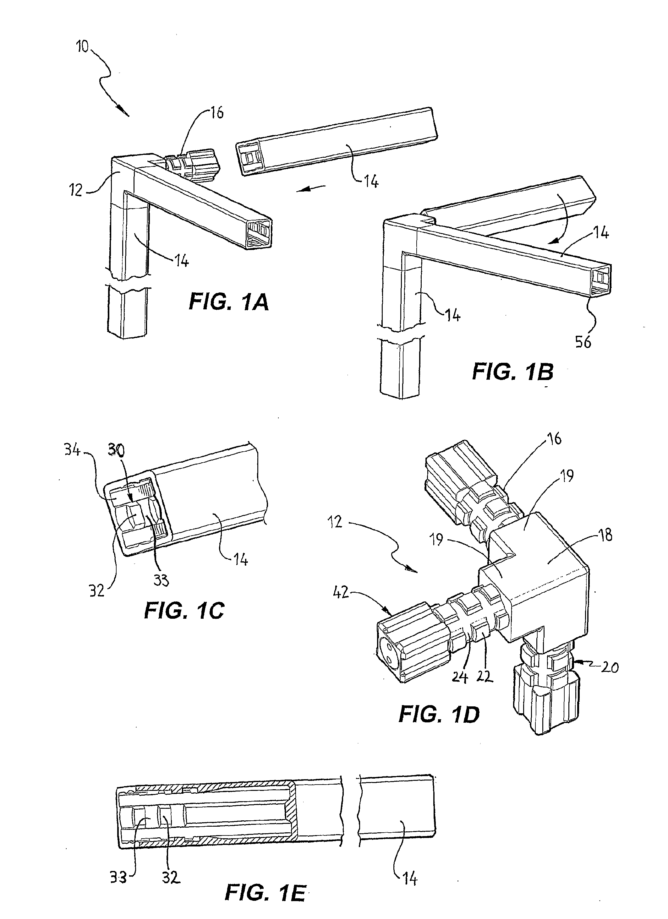
[0065]FIGS. 1A and 1B show a set of components or coupling 10 according to a first embodiment of the present invention. Set or coupling 10 includes a first component, such as connecting member 12 and second components, such as rod members 14. In this embodiment, three rod members 14 are illustrated such that when coupled to the connecting member, a corner of a frame structure is provided.

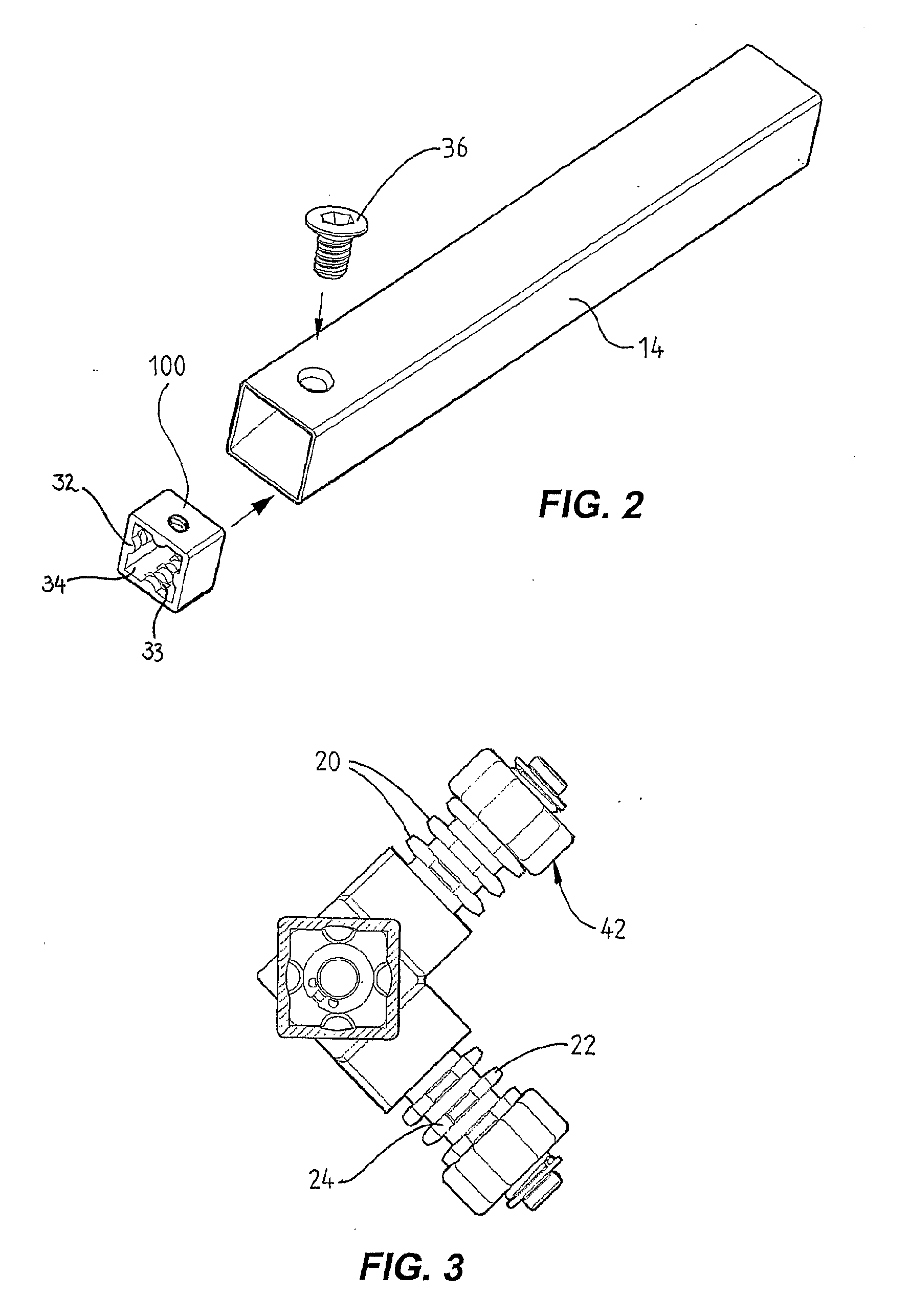
[0066]FIG. 1A shows a rod member 14 prior to connection with the connecting member 12. Connecting member 12 is provided with one or more stub portions 16 that extend outwardly from sides of a central portion 18 of the connecting member 12 (as shown in FIG. 1D). In this embodiment, the connecting member 12 is provided with three stub portions. The central portion 18 is generally cubic and the connecting member 12 includes short arms 19 extending between the central portion 18 and each of the stub portions 16.

[0067]The main shaft of each of the stub portions 16 is of generally circular cross-section a...


PUM


Abstract

A set (10), including a first component (12) having one or more stub portions (16) extending from the first component (12), the one or more stub portions (16) being formed with at least one set of radially extending teeth (22) separated circumferentially by troughs (24), and a second component (14) having a socket portion shaped to receive one of the stub portions (16), wherein peripherally spaced formations (30) are provided on an interior surface of the socket portion. The stub portion (16) is able to be received within the socket of the second component (14) by aligning the teeth (22) of the stub portion (16) between the formations (30) of the socket, and wherein the stub portion and socket are thereafter connected by relatively rotating the first (12) or second components (14) such that the teeth (22) of the stub portion engage the formations (30) of the socket to couple the first and second components together.

Description

FIELD OF THE INVENTION [0001]The present invention is directed to a set of components able to be coupled together. The set can be used for an open frame structure, preferably comprising a plurality of rod or tube members and interconnecting joints for connecting the rod or tube members. In particular, this invention is directed to the method of connecting the components of the set. A frame structure incorporating the set of components has particular application as a shop display structure or shelving system. It will be appreciated that the components that form the set according to the present invention can have various types of applications.BACKGROUND OF THE INVENTION [0002]Frame structures comprising a series of interconnected rod or tube members are well known and are used widely as shop display structures. They offer advantages over pre-assembled structures in that they can be manufactured and transported as smaller units requiring smaller packaging. Their modularity means that t...

Claims


Application Information

Patent Timeline
IPC IPC(8): F16B7/00
CPCA47B47/0016E04B1/5831E04B1/585F16B7/0446F16B7/20F16B12/40Y10T403/342Y10T403/7031Y10T403/7015Y10T403/58Y10T403/7005Y10T403/7016F16B12/44F16B2200/69
Inventor KEYVANLOO, AYDIN
Owner KEYVANLOO AYDIN
Learn More