
Aerodynamic Controls for High Speed Elevators

a technology of aerodynamic controls and elevators, applied in the direction of building lifts, transportation and packaging, etc., can solve the problems of mechanical vibration, degradation of ride quality, and degradation of ride quality

Inactive Publication Date: 2010-01-21
THYSSENKRUPP ELEVATOR CAPITAL CORP
View PDF18 Cites 8 Cited by
  • Summary
  • Abstract
  • Description
  • Claims
  • Application Information

AI Technical Summary

Problems solved by technology

One source of the degradation of ride quality is mechanical vibration resulting from the interaction between elevator guiding members and elevator guide rails.
Another source of the degradation of ride quality is aerodynamic influence resulting from airflow around the elevator car.
As the speed of the elevator car increases, these aerodynamic influences cause vibration, buffeting, and acoustic noise.

Method used


Image

  • Aerodynamic Controls for High Speed Elevators
  • Aerodynamic Controls for High Speed Elevators

Examples


Embodiment Construction

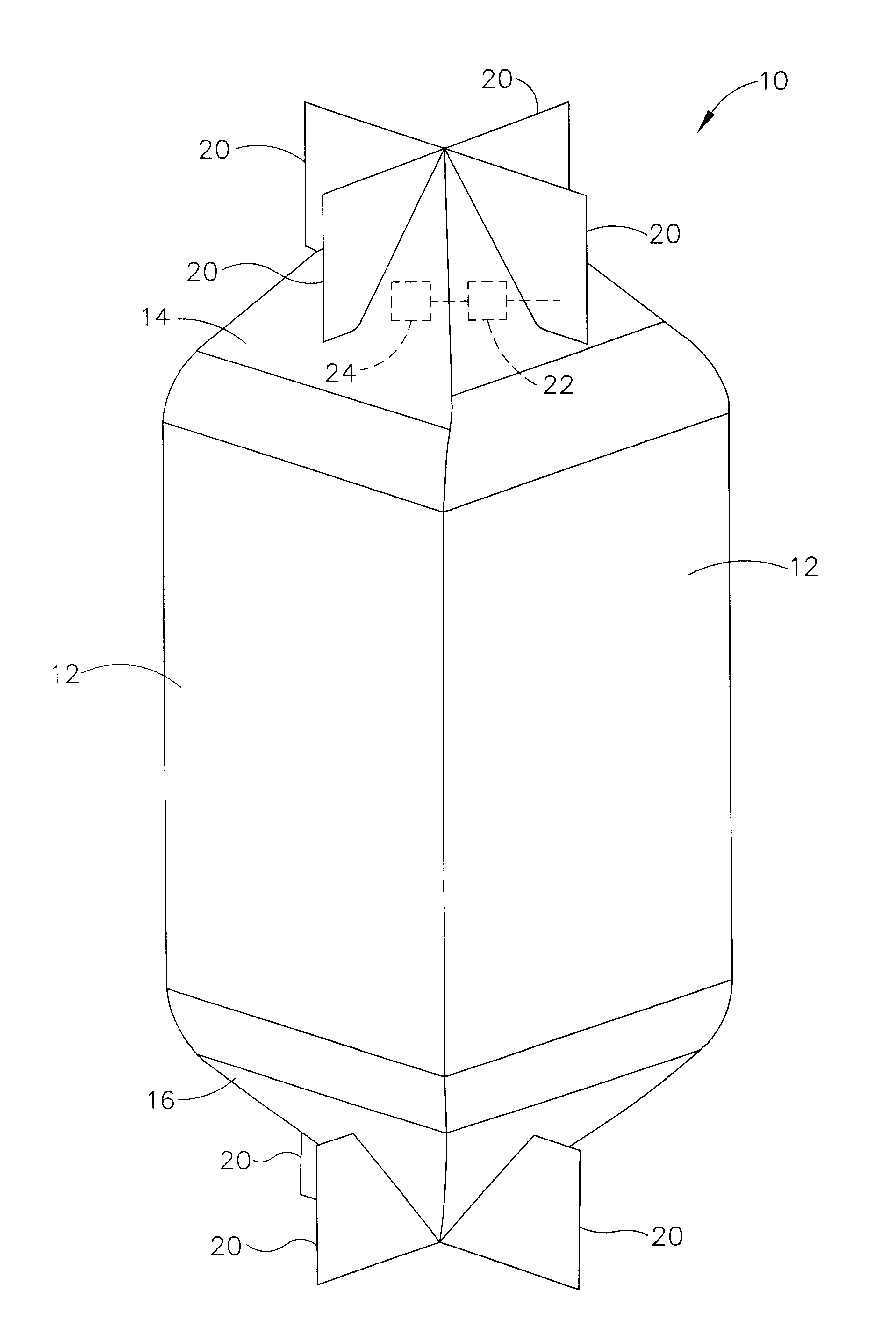
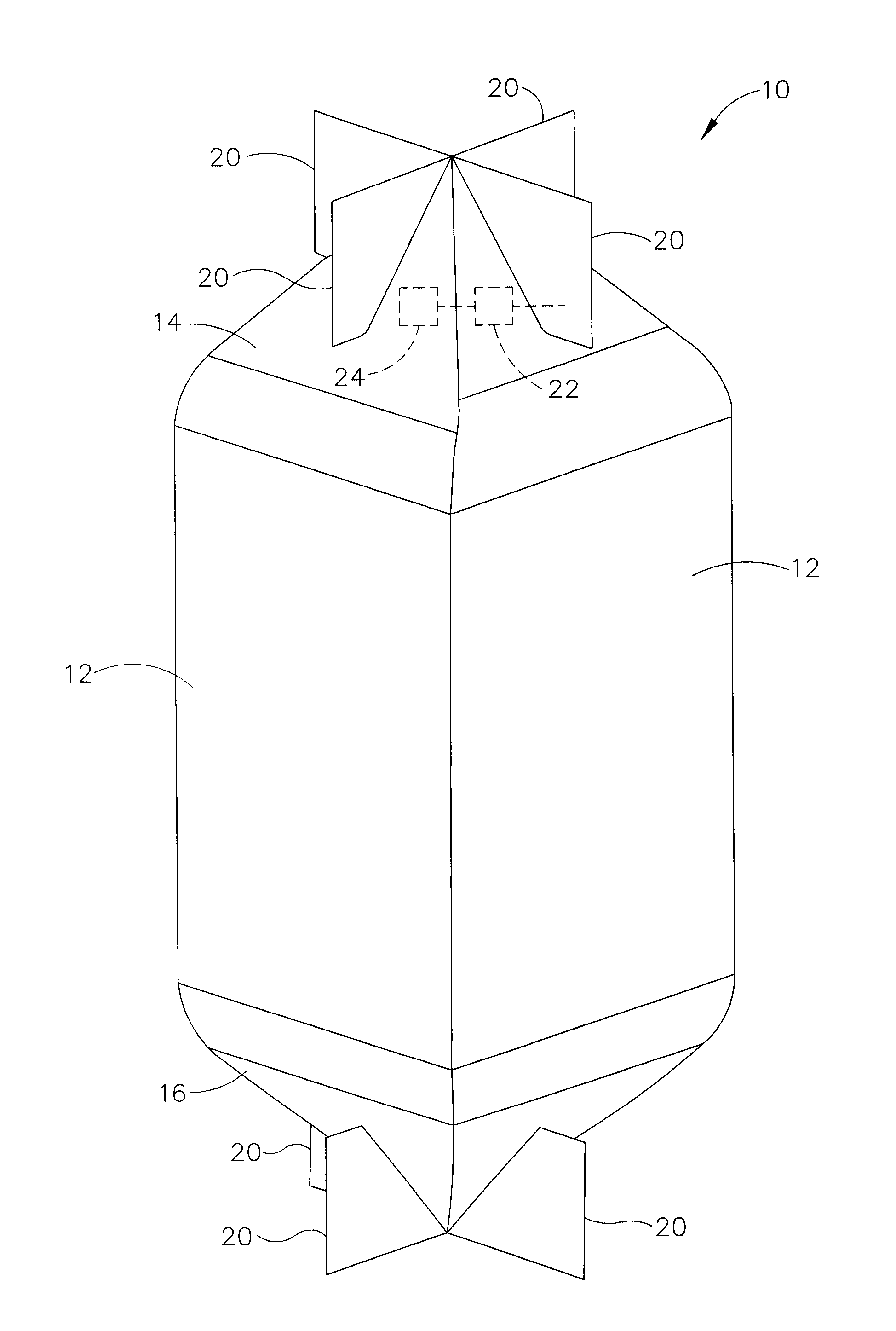
[0006]FIG. 1 shows an embodiment of elevator car 10 configured in accordance with the teachings of the present invention. Elevator car 10 may include four side walls 12. At least one side wall 12 includes an entryway and one or more sliding doors. Elevator car 10 travels within a hoistway and may be driven by any suitable hoisting system known in the art. For example, the hoisting system may be a traction system, a hydraulic system, or the like. In addition, elevator car 10 may include one or more guiding members, each of which slidably engage a corresponding vertically extending guide rail within the hoistway.

[0007]Elevator car 10 may include an aerodynamic surface disposed at either end of elevator car 10 configured in any suitable configuration, such as upper dome 14 secured atop the roof of the elevator car 10, and lower dome 16 secured at the lower end elevator car 10. In the embodiment depicted, each dome 14, 16 is generally pyramid shaped, however, it should be appreciated th...


PUM


Abstract

An elevator car is provided with at least one moveable aerodynamic control surface which is moveable to generate counter forces to aerodynamic forces resulting from airflow around the elevator car. Aerodynamically suitable surfaces may also be provided on either end of the elevator car.

Description

BACKGROUND OF THE INVENTION [0001]Elevator cars are frequently employed to transport loads and / or persons within a short time. As the speed of the elevator car increases, ride quality decreases. One source of the degradation of ride quality is mechanical vibration resulting from the interaction between elevator guiding members and elevator guide rails. As the speed of the elevator car increases, these vibrations are excited, in part, by imperfections in the guide rails. To reduce these vibrations, several solutions have been offered. Active suspension systems, such as those described in U.S. Pat. No. 5,439,075 and U.S. Pat. No. 6,474,449, offer one solution, both of which are incorporated herein by reference. Non-contact systems involving magnets, such as those described in U.S. Pat. No. 5,321,217 and U.S. Pat. No. 5,379,864, offer another solution. Moving mass damping systems, such as those described in U.S. Pat. No. 5,811,743, offer yet another solution.[0002]Another source of the...

Claims


Application Information

Patent Timeline
IPC IPC(8): B66B11/02
CPCB66B11/028B66B11/0226
Inventor SMITH, RORY S.
Owner THYSSENKRUPP ELEVATOR CAPITAL CORP
Learn More