
Compact disk feeding mechanism

a compact disc and feeding mechanism technology, applied in the field of compact disc feeding mechanism, can solve the problems of bulky cd feeding mechanism, difficult assembly, maintenance, repair, etc., and achieve the effect of simple components, easy assembly and maintenan

Inactive Publication Date: 2010-01-14
BLUHEN TECH ENTERPRISE
View PDF10 Cites 0 Cited by
  • Summary
  • Abstract
  • Description
  • Claims
  • Application Information

AI Technical Summary

Benefits of technology

[0006]A primary object of the present invention is to provide a CD feeding mechanism that has simplified components and is easy to assemble and maintain.
[0008]A further object of the present invention is to provide a high-efficient CD feeding mechanism capable of feeding CDs in a time-saving and effortless manner.

Problems solved by technology

The above-described conventional CD feeding mechanism has relatively poor applicability due to the following disadvantages in the practical use thereof:(1) The conventional CD feeding mechanism involves in a large number of very complicated components and is therefore not easy to assemble, maintain, or repair.
Moreover, the large number of complicated components results in a bulky CD feeding mechanism, which could not be widely applied to general commercial and personal applications; and(2) A plurality of procedures, such as vacuum sucking, displacing, releasing vacuum sucking, and returning of the robot, are required in the process of feeding the compact disks to consume a lot of time and efforts.
Therefore, the conventional CD feeding mechanism is low-efficient in the operation thereof.

Method used


Image

  • Compact disk feeding mechanism
  • Compact disk feeding mechanism
  • Compact disk feeding mechanism

Examples


Embodiment Construction

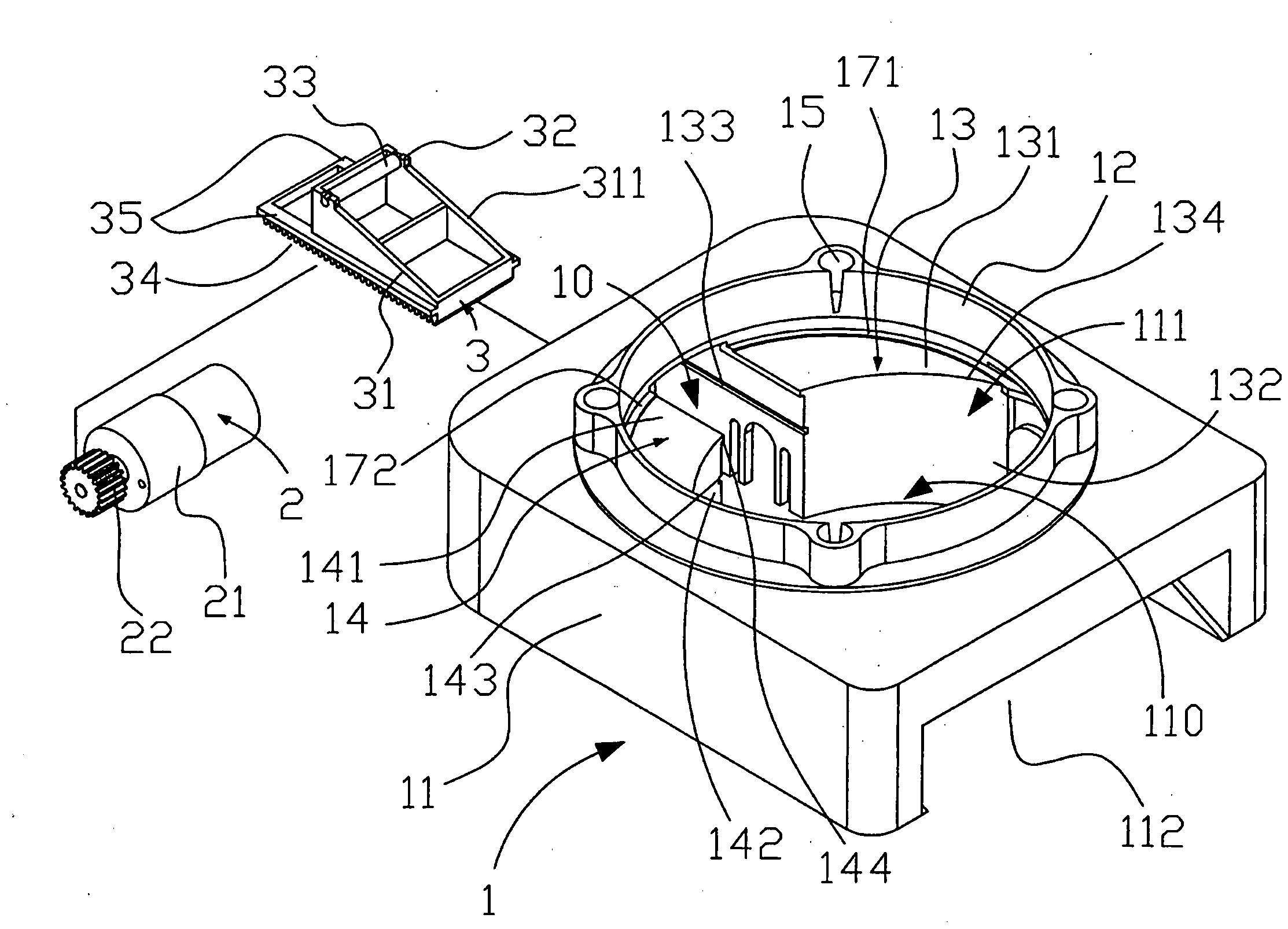
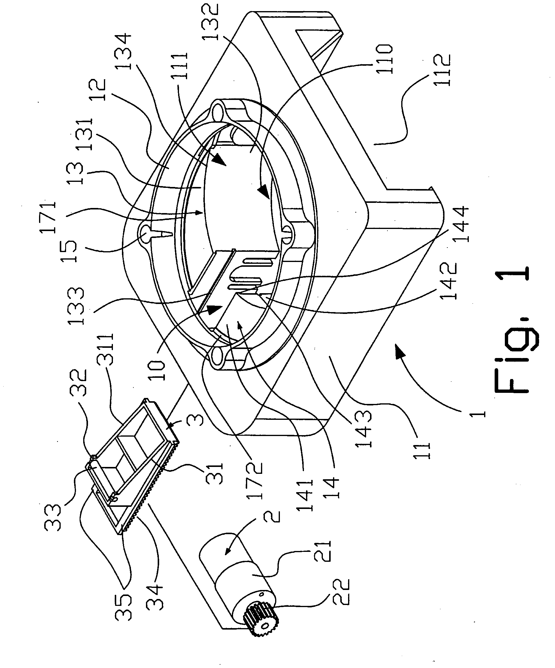
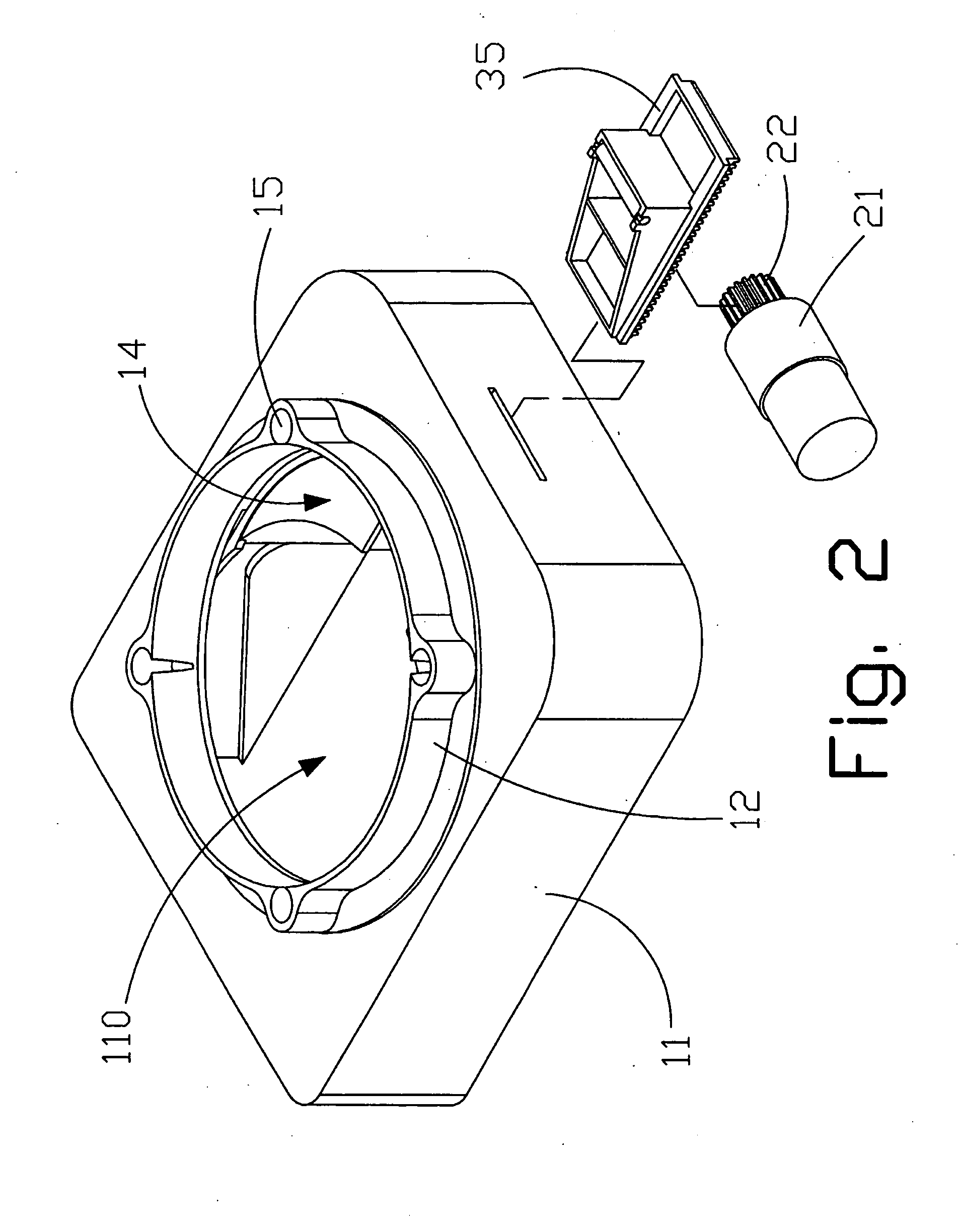
[0028]Please refer to FIGS. 1, 2, 5, and 6, in which a CD feeding mechanism according to a preferred embodiment of the present invention is shown. As shown, the CD feeding mechanism of the present invention includes a base 1, a driving unit 2, and a shifting unit 3.

[0029]In the following description, the phrases “right side”, “left side”, “front side”, and “rear side” shall correspond to the right, left, front, and rear sides of the base 1, respectively, when viewing the base 1 in front of the illustrated FIG. 1.

[0030]The base 1 is configured to carry a plurality of CDs 9 thereon. The base 1 includes a main body 11, an annular wall portion 12, a first supporting wall 171, a second supporting wall 172, a third supporting wall 13, a fourth supporting wall 14, four locating sections 15, and two guiding slopes 18.

[0031]The main body 11 is substantially a rectangular hollow body internally defining a moving passage 110, a CD inlet 111, and a CD outlet 112. The CD inlet 111 is located at ...


PUM


Abstract

A compact disc (CD) feeding mechanism includes a base internally defining a moving passage, and a CD inlet and a CD outlet communicating with an upper and a lower end of the moving passage, respectively, and having a first and a second supporting wall spaced by a shifting path and radially projected into a left side of the CD inlet, an overall length extending along the two supporting walls and the shifting path being larger than one half of the outer circumference of a CD, so that a plurality of CDs may be stacked on the two supporting walls; a driving unit mounted below the base and electrically connected to an external power supply; and a shifting unit including a shifting section driven by the driving unit to shift a lowest one of the stacked CDs out of the supporting walls into the moving passage to the CD outlet.

Description

FIELD OF THE INVENTION[0001]The present invention relates to a feeding mechanism, and more particularly, to a compact disc feeding mechanism capable of automatically feeding a stack of CDs one by one.BACKGROUND OF THE INVENTION[0002]Currently, there are a variety of compact disks available for use, such as standard compact disks (CDs), video compact disks (VCDs), digital versatile disks (DVDs), or even blu-ray disks (BDs). These compact disks have a wide range of applications, such as being used to store multimedia, data, and music. Therefore, these various compact disks have become one of the important data carriers in the modern society.[0003]In the current mass production of various compact disks, blank compact disks are fed using a CD feeding mechanism that controls the operation of a robot, which includes complicated hydraulic linkages, vacuum cup, and many other components. A topmost one of a stack of blank compact disks is sucked by the vacuum cup to achieve the purpose of fe...

Claims


Application Information

Patent Timeline
IPC IPC(8): G11B17/03
CPCG11B17/08
Inventor KANG, HO-CHENGWANG, TZU-YUN
Owner BLUHEN TECH ENTERPRISE
Learn More