
Method Relating To Radio Communication

a radio communication and radio frequency technology, applied in the field of radio communication, can solve the problems of reducing the output power per carrier at the antenna outlet by approximately one-half, wasting radio resources, and usually not being realistic, and achieve the effect of expanding the communication capacity

Inactive Publication Date: 2010-01-07
TELEFON AB LM ERICSSON (PUBL)
View PDF4 Cites 11 Cited by
  • Summary
  • Abstract
  • Description
  • Claims
  • Application Information

AI Technical Summary

Benefits of technology

[0008]An advantage of the above-described method is that no modification of the combiner network is necessary for expansion of communication capacity. Carrier power loss in the sub-sectors is essentially the same before and after expansion of the communication capacity. The method is consequently advantageous for expansion of communication capacity in hybrid-sector structures, since the above-indicated imbalance can be avoided.

Problems solved by technology

In order to align coverage to a common cell boarder, the output power of one or more of the carriers have to be reduced, leading to a potential waste of radio resources.
However, each new combiner level will reduce the output power per carrier at an antenna outlet by approximately one half.
An alternative is to add one or more antennas, but this is usually not a realistic option.
The result is an imbalance in coverage between the antenna beams and the radio sector that must be compensated for by lowering the output power broadcasted in the whole radio sector.

Method used


Image

  • Method Relating To Radio Communication
  • Method Relating To Radio Communication
  • Method Relating To Radio Communication

Examples


Embodiment Construction

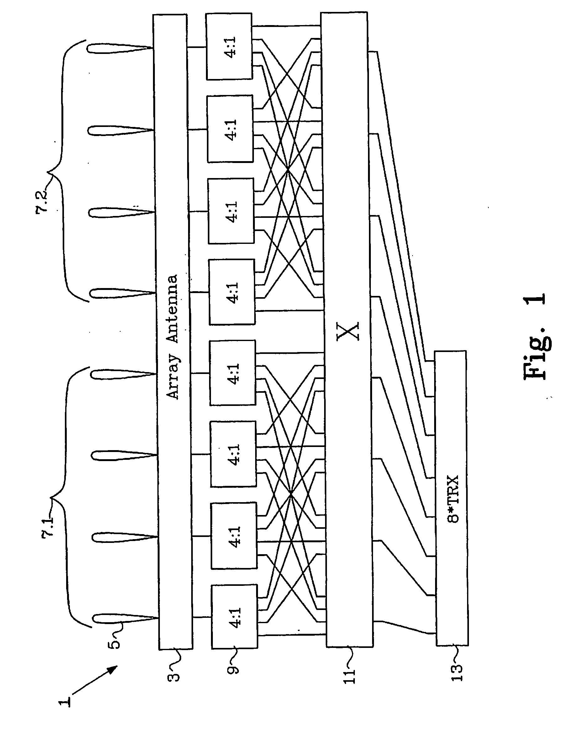
[0013]FIG. 1 shows a block diagram of a radio communication system for 1 a BTS. The radio communication system 1 includes a multi-beam antenna system 3, here embodied as an array antenna. The multi-beam antenna system 3 is arranged for providing a number of antenna beams 5 which are divided into antenna beam groups, where each antenna beam group includes at least one of the antenna beams 5. Each group of antenna beams provides coverage in a respective sub-sector of a radio sector served by the radio communication system 1. In the example of FIG. 1, there are eight antenna beams, which are divided into two antenna beam groups, with four antenna beams in each group. Consequently, in the example of FIG. 1, the radio sector includes two sub-sectors 7.1 and 7.2, which are illustrated schematically by brackets in FIG. 1. The radio communication system 1 of FIG. 1 further includes a transceiver bank 13, here including eight transceivers providing carriers, e.g. for traffic channels. Each c...


PUM


Abstract

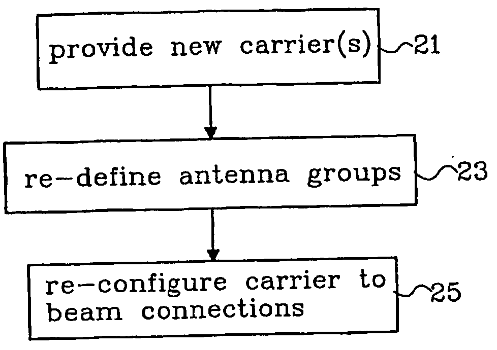
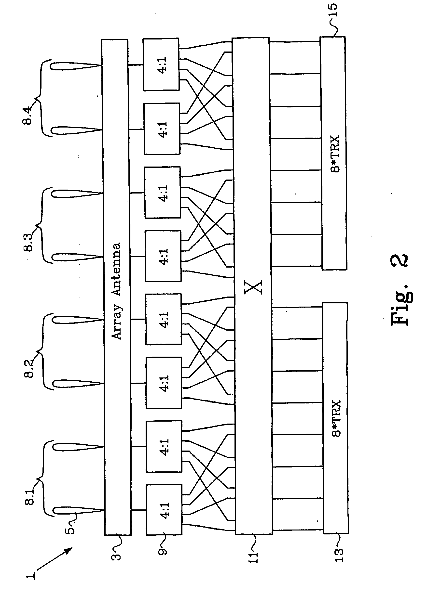
A method for expansion of communication capacity in a radio communication system (1) including a multi-beam antenna system (3) is described. The antenna beams (5) are divided into groups, where the geographical coverage of each group defines a respective sub-sector (7.1,7.2). The sub-sectors in conjunction provide coverage in a radio sector serviced by the communications system (1). A number of carriers are connected to the multi-beam antenna system (3) via a switch (11) and a combiner network (9). The switch (11) allows each carrier to be selectively switched to the sub-sectors via the combiner network (9). In order to expand communication capacity, at least one new carrier is provided. The antenna beam groups and the respective sub-sectors are re-defined such that the number of sub-sectors 15 (8.1-8.4) is increased. In response to the re-definition of the antenna beam groups and sub-sectors (8.1-8.4), carrier to beam connections are re-configured.

Description

TECHNICAL FIELD[0001]The present invention pertains to the field of radio communication; and more particularly to the part of this field which is concerned with variation of communication capacity in radio communication systems which employ a multi-beam antenna system.BACKGROUND AND RELATED ART[0002]A modern BTS (Base Transceiver Station) often includes a multi-beam antenna system capable of producing an plurality of antenna beams. The BTS is adapted to cover one or more radio sectors. The radio sector may in turn be divided into sub-sectors, where each sub-sector consists of a coverage area defined by one or more of the antenna beams produced by the multi-beam antenna system.[0003]A hybrid-sector structure is a sector area that is covered by one carrier containing, for example, the BCCH (BroadCast Control Channel) and two or more sub-sectors, each capable of containing one or more traffic channel carriers. In the hybrid-sector structure, the possible range for coverage can differ s...

Claims


Application Information

Patent Timeline
IPC IPC(8): H04W74/02
CPCH01Q1/246H01Q25/00H01Q3/24
Inventor LORENTZON, STAFFAN
Owner TELEFON AB LM ERICSSON (PUBL)
Learn More