
System for voltage regulation, control protection and monitoring of state of changers under power transformer load, voltage regulators, capacitor banks and similar

a technology of voltage regulation and control protection, which is applied in the direction of electric variable regulation, ac network circuit arrangement, instruments, etc., can solve the problems of limiting existing voltage relays, transformers serving consumers in different loads, and ideal parameter settings for a type of consumer may be totally unsuitable for another type of consumer, and the load is too high or too voltag

Inactive Publication Date: 2010-01-07
SANTOS EDUARDO PEDROSA
View PDF10 Cites 26 Cited by
  • Summary
  • Abstract
  • Description
  • Claims
  • Application Information

AI Technical Summary

Problems solved by technology

One of the limitations of existing voltage relays is related to transformers serving consumers in different load profiles, such as residential, business and industrial consumers.
In this way, ideal parameter settings for a type of consumer may be totally unsuitable for another type of consumer.
With currently available voltage relays there is no satisfactory solution for this occurrence, forcing the operator to favor a certain type of consumer in detriment of another or, then make periodic manual changes to the voltage relay parameter settings.In conventional voltage relays used in transformers, one of the programmed parameters for making the voltage regulation is to delay CDC operation in order to correct voltage that, has as a function preventing unnecessary tap changes is important due to the fact that the CDC is the equipment that generates the highest maintenance costs in transformers and, the need for maintenance in the CD is basically determined by the number of trap changes made.
This forces the operator to adjust timing in order to meet or exceed arbitrarily defined times by the regulatory agency, which usually tends to cause unnecessary additional CDC actuations when adjustment made takes a shorter actuation time than required by the regulatory agency.On-Load Tap Changers (CDC) are equipped with a motorized drive mechanism that receives command signals to increase or decrease the tap position.
Certain failures in referred control elements can lead the CDC to make unsolicited tap changes, which may be repeated in successive manner leading the CDC to reach an extreme upper or lower position, causing either too high or too voltage values in the load.
The occurrence of this type of occurrence is highly undesirable by consequences that may be, for example, load shutoff by its protection actuation or even damages in loads.Following the same above-mentioned context, of the Changers (CDCs) motorized drive mechanism, certain failures may lead the CDC not to make requested tap changes by the voltage regulation system, which may lead voltage in the load to slowly vary as load current and primary voltage in transformer are changed.
After some time, voltage in load may reach very high or very low due to lack of voltage correction that would be provided by CDC operation, with consequences that may go from load shutoff by actuation of its protections or even damages in load.
Currently, maintenance in CDCs is focused on their number of operations, which opens the possibility of problems appearing in CDCs, if interrupted currents by their contacts have sufficient intensity to cause excessive contact wear, anticipating the number of operations predicted for maintenance.
Currently this verification is manually made by the operator, therefore, being subject to human failure.In conventional relays where operation control in parallel of transformer banks consisting of single-phase transformers is done, it is necessary to ensure, during normal operation, that the three single-phase transformers of which a bank consists are with their CDCs in the same tap position.
This selection is made manually, which opens the possibility for an operator error, which may select the transformer CDC of each phase to operate in individual manner, and consequently in different tap position from the other phases, even if the transformer bank is in normal operation electrically connected in parallel to other banks.In existing systems where operation control in parallel of transformer banks consisting of single-phase transformers is done, a synchronism checking is made between tap positions of the three single-phase transformers of the same bank, blocking CDC operation and issuing an alarm if a tap discrepancy occurs between the bank phases.

Method used


Image

  • System for voltage regulation, control protection and monitoring of state of changers under power transformer load, voltage regulators, capacitor banks and similar
  • System for voltage regulation, control protection and monitoring of state of changers under power transformer load, voltage regulators, capacitor banks and similar
  • System for voltage regulation, control protection and monitoring of state of changers under power transformer load, voltage regulators, capacitor banks and similar

Examples


Embodiment Construction

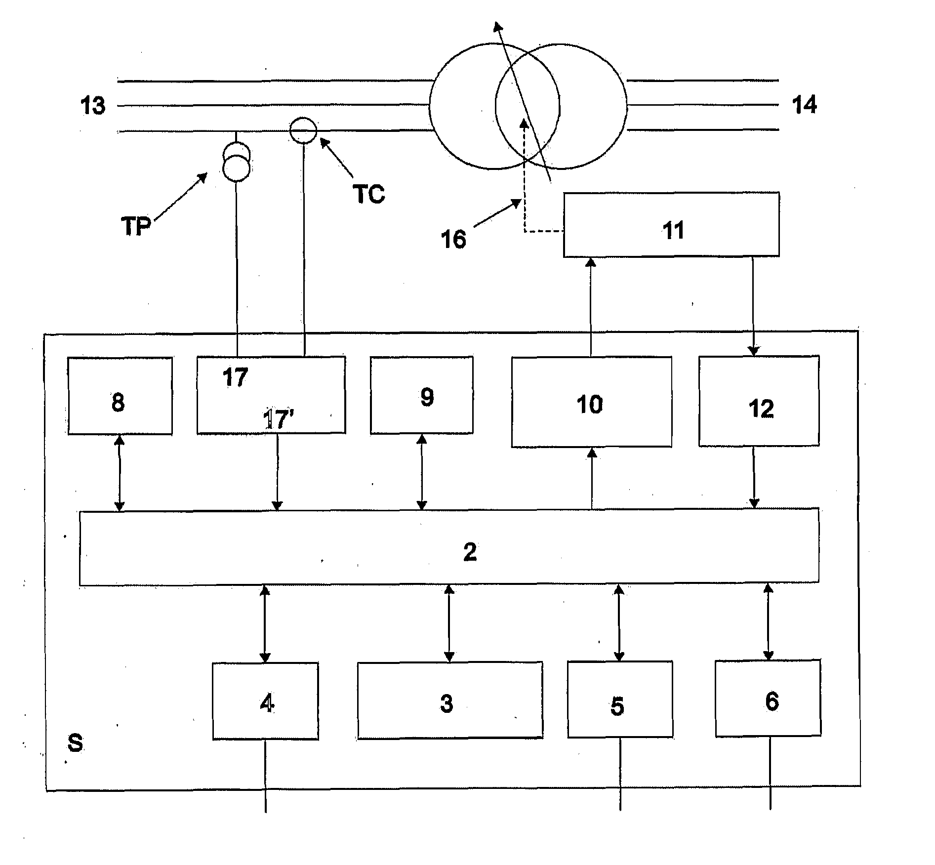
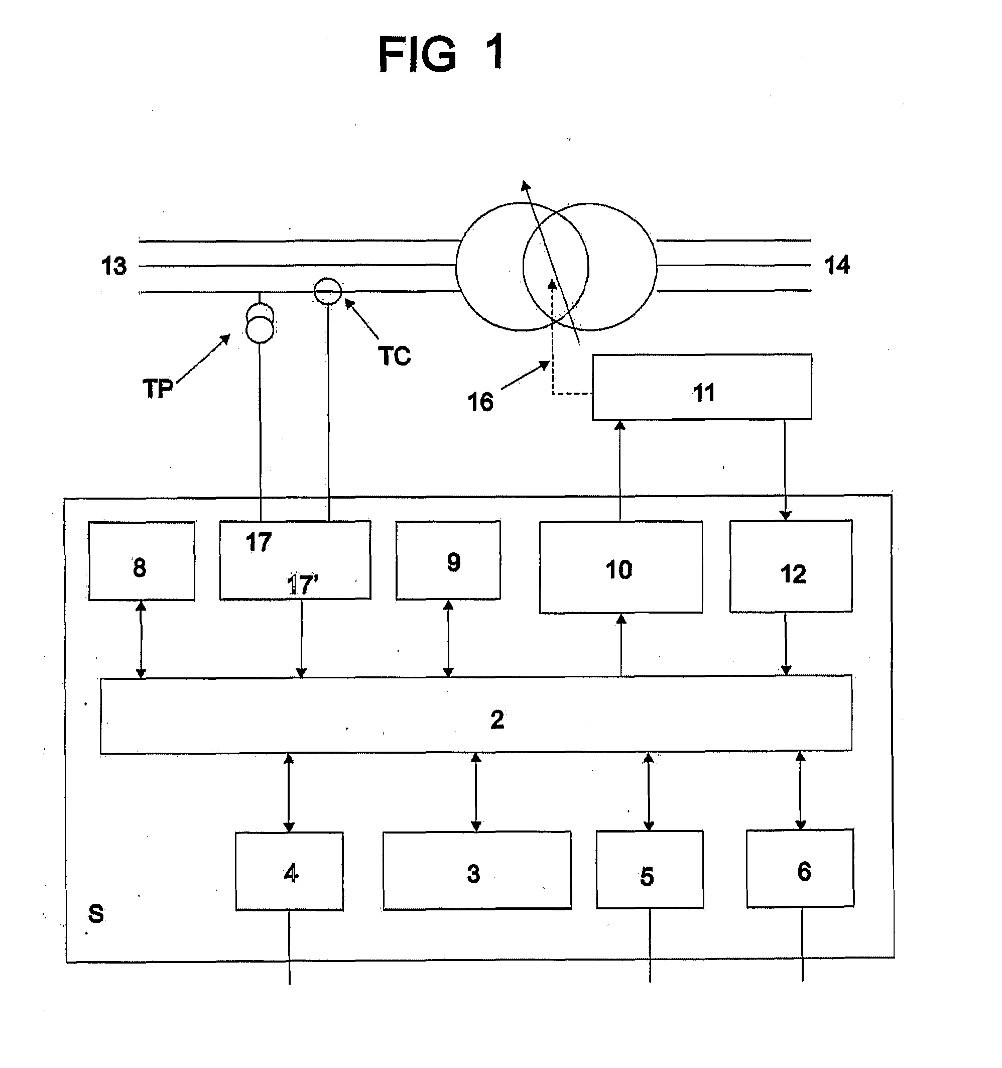
[0039]The “SYSTEM FOR VOLTAGE REGULATION, CONTROL, PROTECTION AND MONITORING OF STATE OF CHANGERS UNDER POWER TRANSFORMER LOAD, VOLTAGE REGULATORS, CAPACITOR BANKS AND SIMILAR”, covered by this Invention patent application, preferably applies to power transformers (1) and voltage regulators and similar, it being that this system (S) hereinafter referred to as voltage regulation system, by means of a microprocessor (2) provides innovating functions that make up for deficiencies of currently existing voltage relays, highlighting pre-programming, by means of man-machine interface such as, for example, keyboard and display (3), or serial communication (4) of several settings and different voltage regulation parameters, each adequate setting for a certain prevailing load condition, performed by means of dry contact inputs (5), contact outputs (6) being destined for self-diagnosis signaling and alarms (7). Voltage regulation allows parameter selection to be made by means of daily and hour...


PUM


Abstract

System for voltage regulation, control, protection and monitoring of state of changers under power transformer load, voltage regulators, capacitor banks and similar”, is preferably applied to power transformers (1) and voltage regulators and similar, through a microprocessor (2) it provides innovating functions that make up for deficiencies of currently existing voltage relays, highlighting pre-programming, by means of man-machine interface such as, for example, keyboard and display (3), or serial communication (4) of several settings and different voltage regulation parameters, each adequate setting for a certain prevailing load condition, performed by means of dry contact inputs (5), contact outputs (6) destined for self-diagnosis signaling and alarms (7); voltage regulation allows parameter selection to be made by means of daily and hourly programming through an internal clock (8); said system (S) also has the non-volatile memory function (9); CDC blocking function (10) that directly acts on the motorized drive (11) of the CDC; and maintenance assistant functions of the changer under load (10).

Description

BRIEF INTRODUCTION[0001]This Invention patent application deals with an unheard of “SYSTEM FOR VOLTAGE REGULATION, CONTROL, PROTECTION AND MONITORING OF STATE OF CHANGERS UNDER POWER TRANSFORMER LOAD, VOLTAGE REGULATORS, CAPACITOR BANKS AND SIMILAR” remarkably with a voltage regulation system, provided with innovating functions and features that enable making up for deficiencies of currently used voltage relays, by preserving unbiased treatment to consumers, residential or business irrespective of demand curve variations.BRIEF BACKGROUND[0002]Power transformers and autotransformers and voltage regulators are used in an electric power generation, transmission and distribution system for power transfer, normally changing the output voltage value in relation to input. In order to allow controlling voltage supplied to load, its windings are equipped with taps which are connected to a CDC or OLTC (On-Load Tap Changer), which makes TAP change used with the energized transformer and with c...

Claims


Application Information

Patent Timeline
Patent Type & Authority Applications(United States)
IPC IPC(8): G05F1/147
CPCG05F1/14Y02E40/30H02J3/1878G05F1/147H02M3/33507
Inventor SANTOS, EDUARDO PEDROSA
Owner SANTOS EDUARDO PEDROSA
Learn More