
Use of registration marks and a linear array sensor for in-situ raster output scanner scan line nonlinearity detection

a technology of linear array sensor and registration mark, which is applied in the direction of electrographic process apparatus, instruments, printing, etc., can solve the problems of inability to register colors in multiple ros laser printers, deviations from the uniform grid, and difficulty in obtaining evenly spaced pixels

Active Publication Date: 2009-12-31
XEROX CORP
View PDF14 Cites 16 Cited by
  • Summary
  • Abstract
  • Description
  • Claims
  • Application Information

AI Technical Summary

Benefits of technology

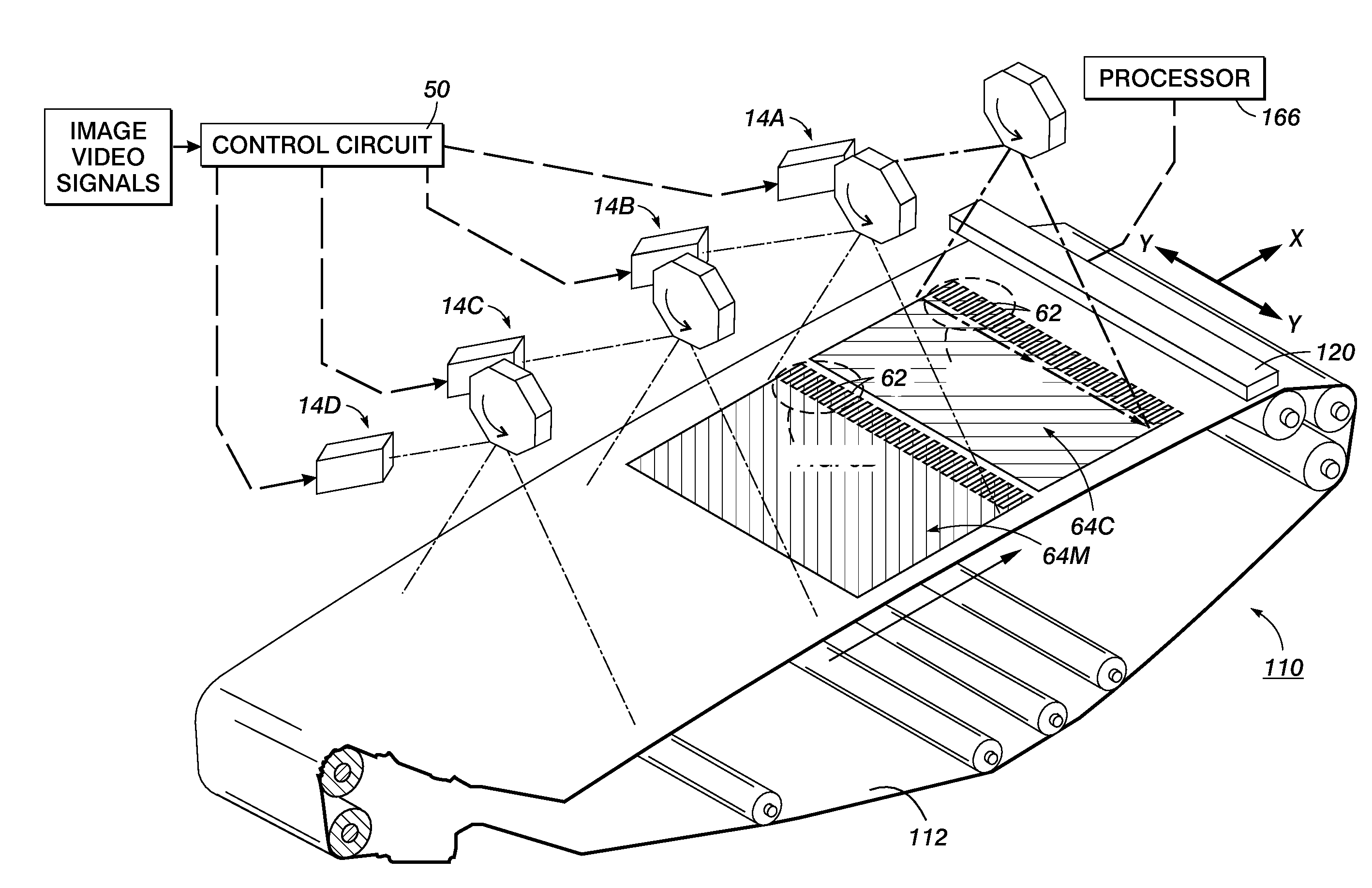
The patent describes a method and system for correcting errors in image printing. The system includes a print engine that places marking material on a moving surface to create a row of registration marks. A linear array sensor detects the position of these marks, and a processor uses this information to create a correction function to compensate for any errors in the position of the marks. This results in a more accurate and precise image printing process.

Problems solved by technology

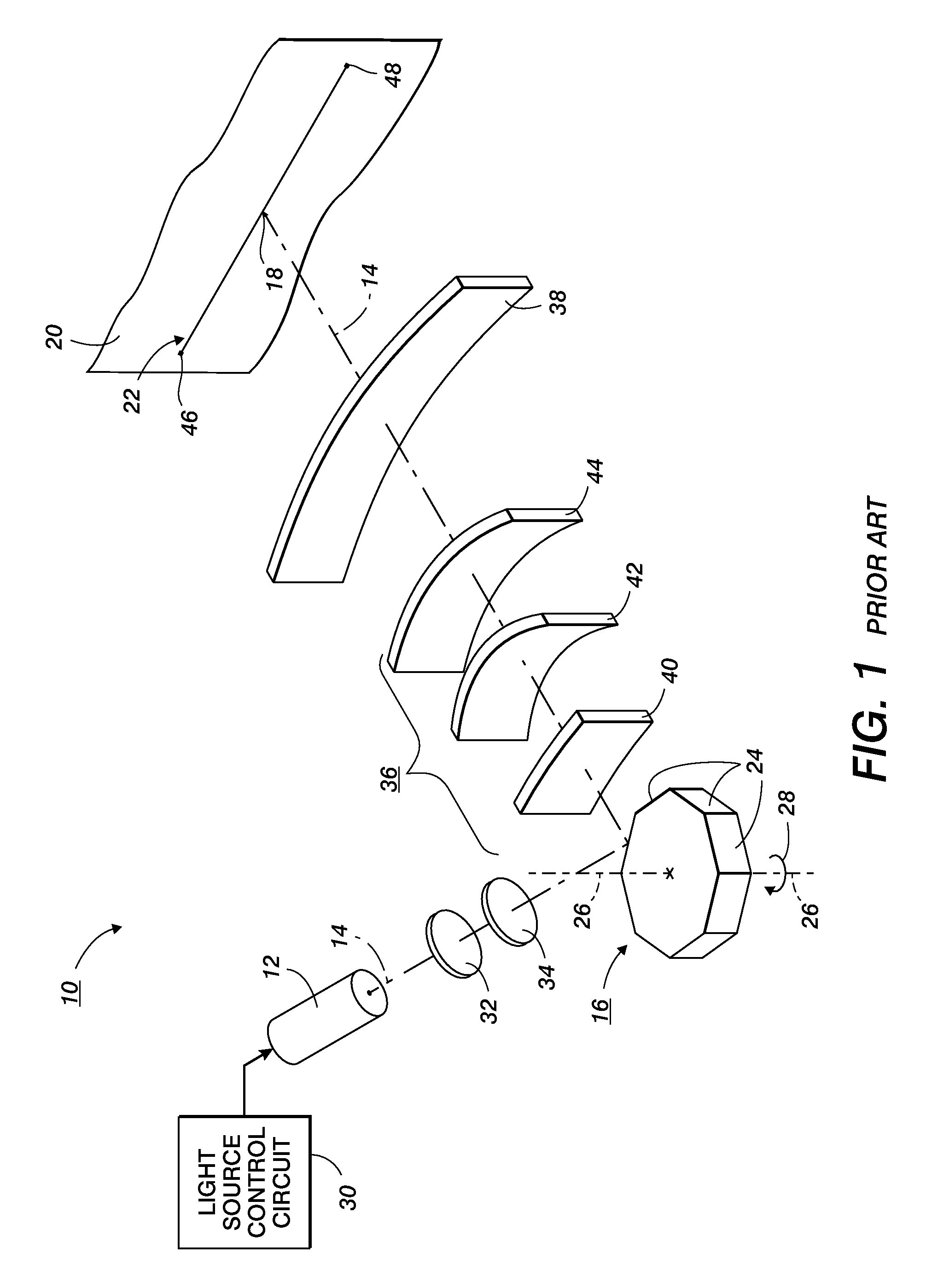
However, because of the inherent geometry of the optical system of the ROS, and because manufacturing errors can cause imperfections in the facets of a polygon mirror, obtaining evenly spaced, identical pixels can be problematic.
The shape of the non-linearity signature varies from ROS to ROS and can thus cause misregistration between colors in a multiple ROS laser printer.
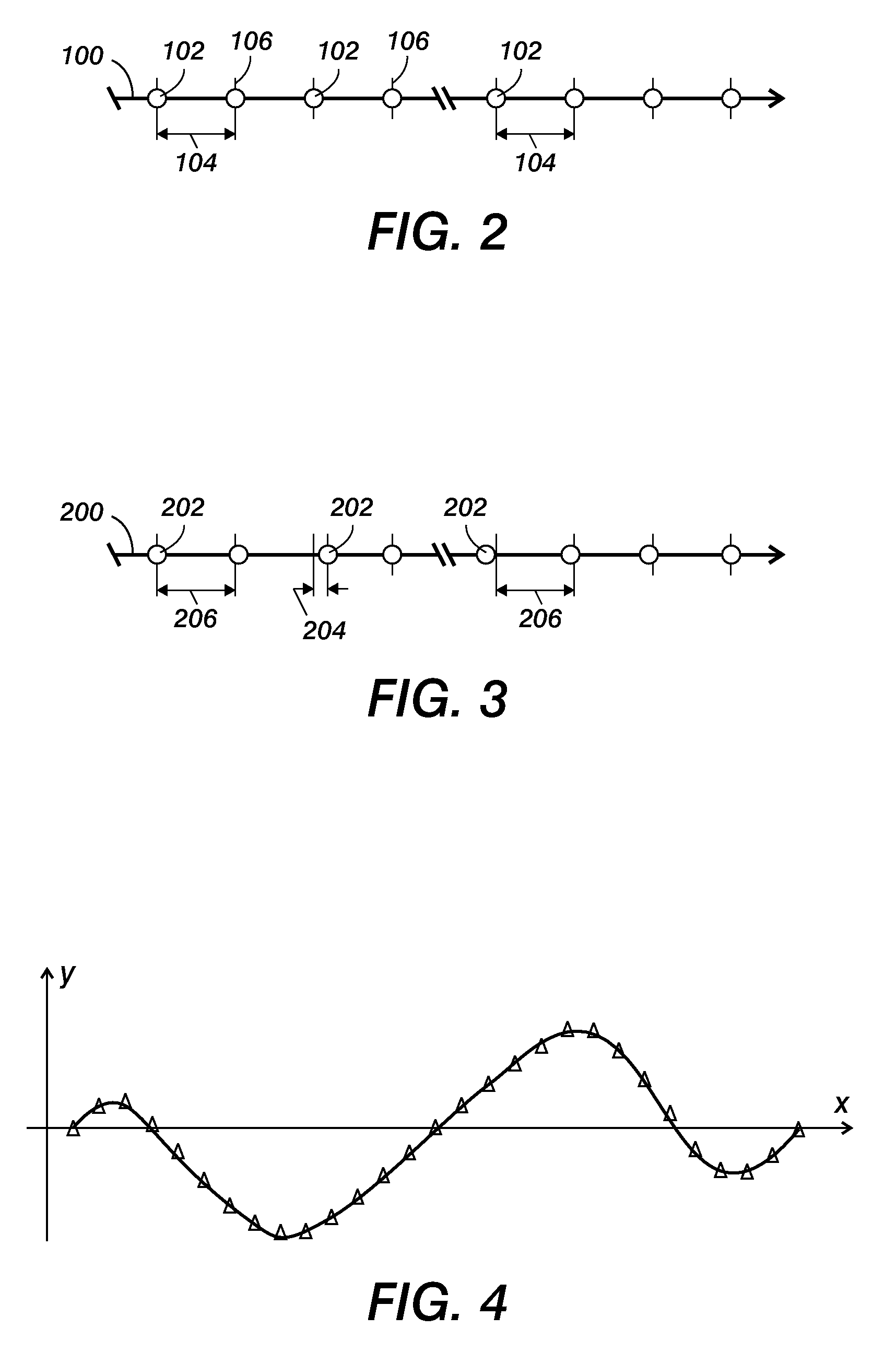
In practice, the raster output scanning system has a small non-linearity, which causes deviations from the uniform grid.
The inherent scan non-linearity in the ROS if uncorrected will improperly space pixels along the scan line direction.
This process is fairly labor intensive for the Field Service Engineer and is prone to error.
This patent, however, does not disclose automatically detecting and measuring the non-linearities of the scan line.

Method used


Image

  • Use of registration marks and a linear array sensor for in-situ raster output scanner scan line nonlinearity detection
  • Use of registration marks and a linear array sensor for in-situ raster output scanner scan line nonlinearity detection
  • Use of registration marks and a linear array sensor for in-situ raster output scanner scan line nonlinearity detection

Examples


example

[0062]If registration marks are to be imaged by a ROS at the following locations from an edge of a paper (e.g., measured in inches)

ABCD. . .YZ1.01.52.02.5. . .9.510.0

[0063]The scan non-linearity error in the ROS may cause the registration marks to be imaged at the following locations from the edge of the paper (in inches)

ABCD. . .YZ1.11.452.012.61. . .9.499.95

[0064]Using the present disclosure the positions in the cross-process direction of the registration marks (e.g., A-Z) on the image bearing surface can be detected using the linear array sensor. The error between the desired positions in the cross-process direction of the registration marks (e.g., where they should have been placed) and the actual positions in the cross-process direction of the registration marks (e.g., where they are actually placed) is characterized by a correction function (e.g., a polynomial curve). The correction function is then integrated into a controller of the ROS. When imaging the pixels (e.g., regist...


PUM


Abstract

A method for detecting, in-situ, a cross-process linearity error in an image printing system that prints on an image bearing surface movable in the process direction is provided. The method includes placing marking material to form of a row of registration marks on the image bearing surface, detecting a position in a cross-process direction of each registration mark in the row using a linear array sensor that extends in the cross-process direction, and determining a correction function with a processor using the positions of the registration marks as detected by the linear array sensor to compensate for an error in the positions in the cross-process direction of the registration marks. The row of registration marks extends in a cross-process direction transverse to the process direction.

Description

BACKGROUND[0001]1. Field[0002]The present disclosure relates to a system and a method for detecting, in-situ, a cross-process linearity error in an image printing system that prints on an image bearing surface movable in the process direction.[0003]2. Description of Related Art[0004]Image printing systems in which a laser scan line is projected onto an image bearing surface to reproduce information are well known in the art. The image printing system typically uses a Raster Output Scanner (ROS) as a source of signals to be imaged on a pre-charged photoreceptor (e.g., a photosensitive plate, belt, or drum) for purposes of xerographic printing. The ROS provides a laser beam which switches on and off as it moves, or scans, across the photoreceptor. The surface of the photoreceptor is selectively discharged by the laser in locations to be printed, to form the desired image on the photoreceptor. The on-and-off control of the beam to create the desired latent image on the photoreceptor is...

Claims


Application Information

Patent Timeline
Patent Type & Authority Applications(United States)
IPC IPC(8): B41J2/435B41J2/47
CPCB41J2/473
Inventor CALAMITA, JAMES PATRICKMARTIN, MICHAEL J.
Owner XEROX CORP
Learn More