
Electronic manometer for appropriately adjusting internal pressure of cuff and method for controlling the same

a technology of internal pressure and manometer, which is applied in the field of electronic manometer, can solve the problems of troublesome handling, inability to measure blood pressure for every heart beat, and pressure sensor not necessarily matching intra-arterial pressur

Inactive Publication Date: 2009-12-17
OMRON HEALTHCARE CO LTD
View PDF27 Cites 21 Cited by
  • Summary
  • Abstract
  • Description
  • Claims
  • Application Information

AI Technical Summary

Benefits of technology

[0020]In view of the above situations, it is an object of the present invention to determine a control target value in a short period of time in an electronic manometer for measuring the blood pressure using a volume compensation method.Means for Solving the Problems

Problems solved by technology

In such blood pressure measurement method, the internal pressure of the cuff needs to be gradually depressurized to determine the systolic blood pressure and the diastolic blood pressure, and thus the measurement time for one measurement requires about thirty seconds at the fastest, and it is impossible to measure the blood pressure for every heart beat.
Actually, it is impossible to compress only the artery, and the tissues of the body surface are also simultaneously compressed, and thus the pressure detected by the pressure sensor does not necessarily match the intra-arterial pressure.
Furthermore, the sensor needs to be correctly arranged on the artery to flatly compress the artery, and thus it is very troublesome to handle, and is used only in a limited state such as during a surgery or when treating in an intensive case after the surgery.

Method used


Image

  • Electronic manometer for appropriately adjusting internal pressure of cuff and method for controlling the same
  • Electronic manometer for appropriately adjusting internal pressure of cuff and method for controlling the same
  • Electronic manometer for appropriately adjusting internal pressure of cuff and method for controlling the same

Examples


Embodiment Construction

[0060]An embodiment of an electronic manometer according to the present invention will be described below with reference to the drawings.

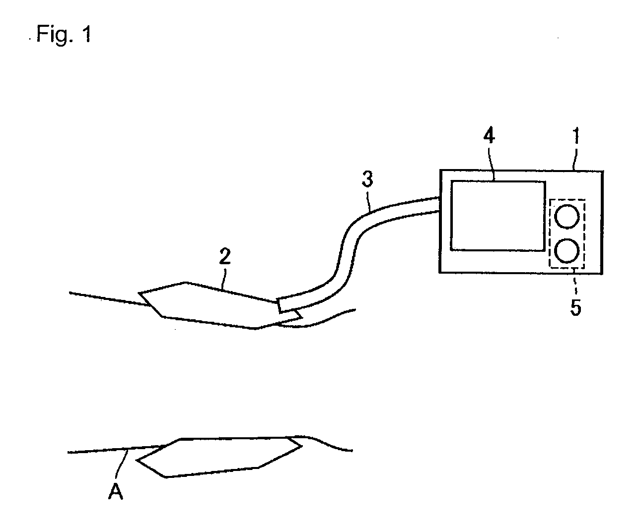
[0061]FIG. 1 is an overview diagram of an electronic manometer according to one embodiment of the present invention.

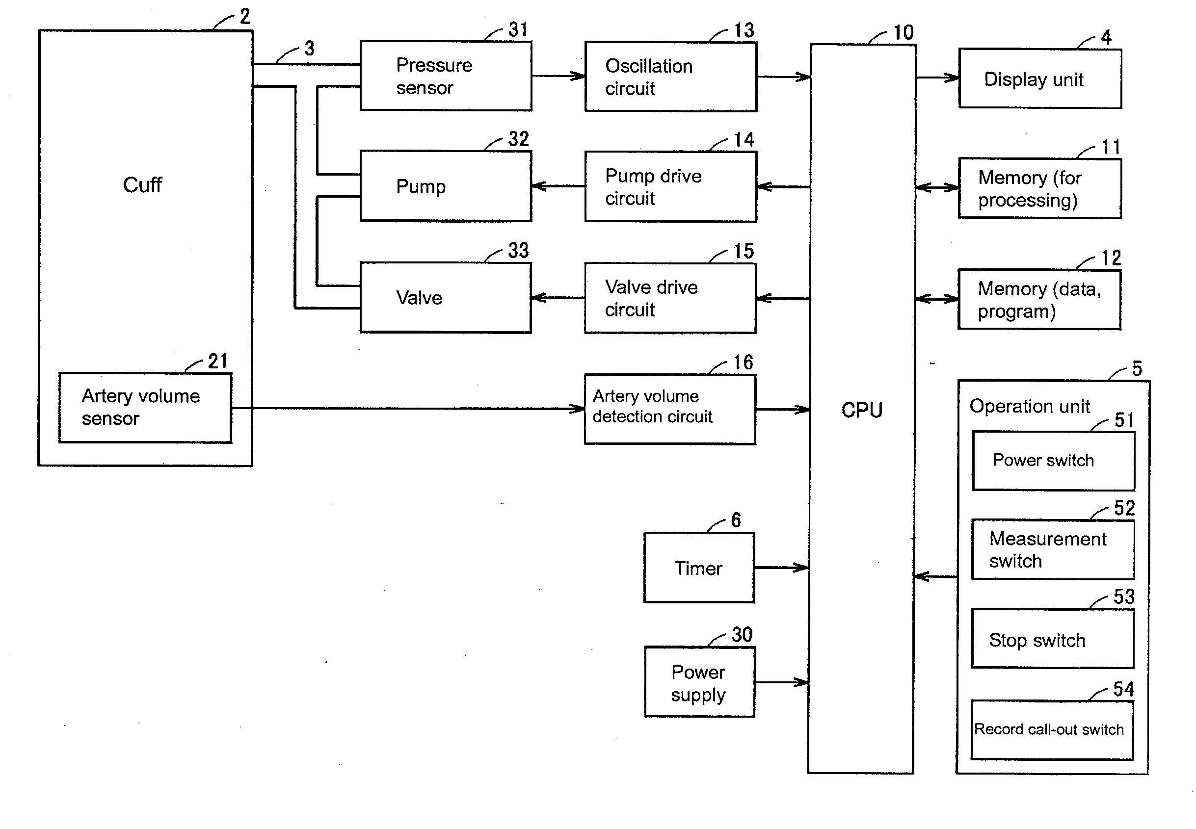
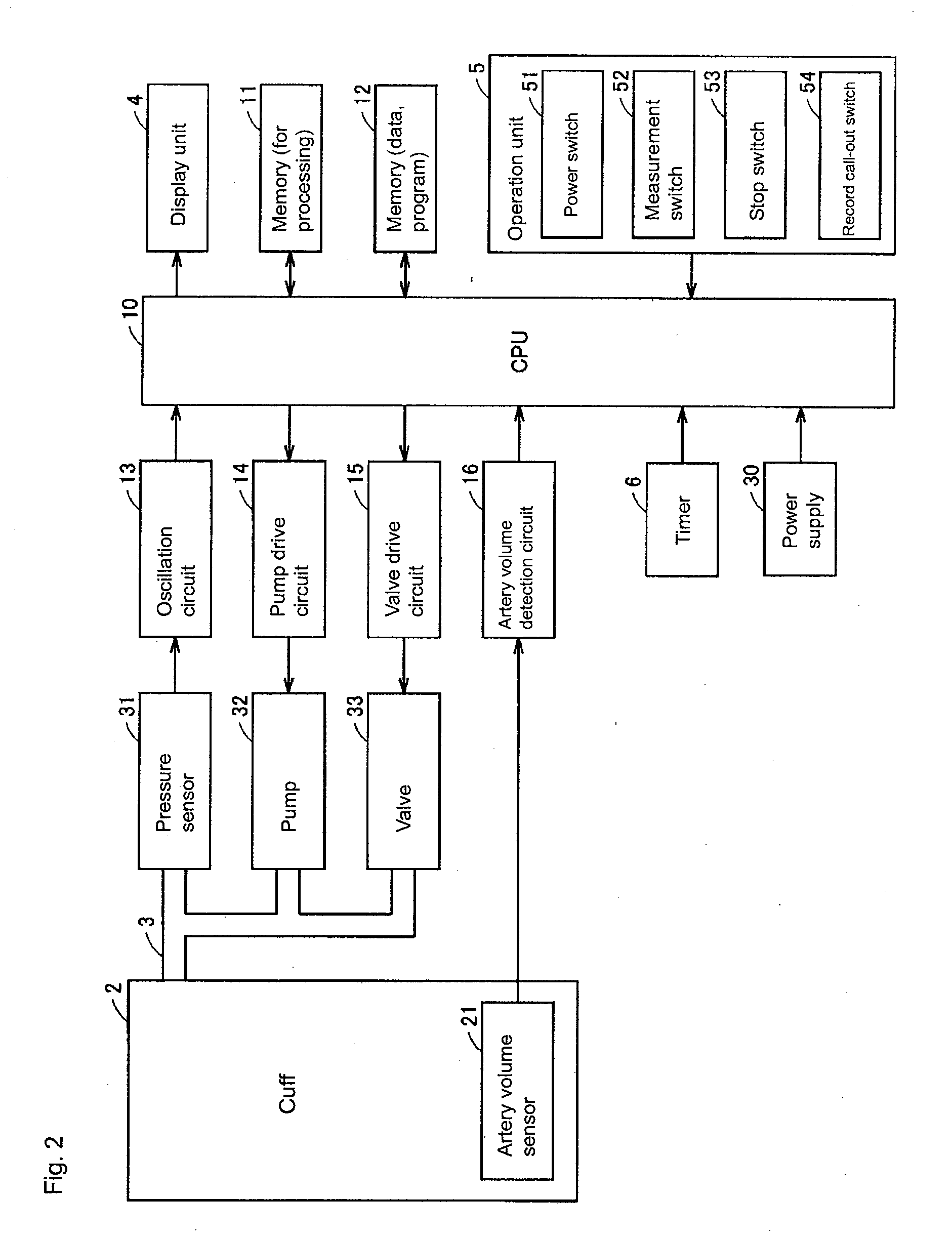
[0062]The electronic manometer 1 includes a cuff 2, and measures blood pressure of a measurement subject with the cuff 2 wrapped around a wrist A of the measurement subject. In the electronic manometer according to the present invention, a measurement site of the blood pressure is not limited to the wrist. The measurement sites may be a fingertip, an upper arm, and the like as long as a volume of an artery can be detected, as hereinafter described.

[0063]The electronic manometer 1 is arranged on a front surface with a display unit 4 and an operation unit 5 with a plurality of operation buttons. The electronic manometer 1 also includes a tube 3 for connecting a built-in pump (later-described pump 32) and the cuff 2. The cuff 2 internall...


PUM


Abstract

An electronic manometer detects pressure within a cuff at which an amplitude of change in a volume of an artery of a measurement subject becomes a maximum by detecting volume of an artery of a measurement subject while superimposing a vibration of high frequency during a period of raising the pressure to apply on the cuff or during a period of lowering after raising to greater than or equal to a systolic blood pressure of the measurement subject. The electronic manometer controls the pressure to apply on the cuff so that the volume of the artery of the measurement subject becomes constant, and measures the blood pressure of the measurement subject from an increased or decreased value of the pressure to apply.

Description

[0001]This application is a National Stage application of PCT / JP2007 / 064324, filed Jul. 20, 2007, which claims the benefit of priority of Japanese Application No. 2006-212090, filed Aug. 3, 2006, the entire contents of these applications hereby incorporated by reference.TECHNICAL FIELD[0002]The present invention relates to an electronic manometer and a method for controlling the same, in particular, to an electronic manometer for measuring blood pressure using a volume compensation method, and a method for controlling the same.BACKGROUND ART[0003]Blood pressure is one index for analyzing cardiovascular disorder, where performing risk analysis based on the blood pressure is effective in preventing cardiovascular diseases such as stroke, cardiac arrest, and cardiac infarction. In particular, morning hypertension in which the blood pressure rises in early morning is related to heart disease, stroke, and the like. Furthermore, it is known that in the morning hypertension, a symptom in w...

Claims


Application Information

Patent Timeline
IPC IPC(8): A61B5/0225
CPCA61B5/02255A61B5/02141
Inventor YAMAKOSHI, KENICHITANAKA, SHINOBUNOGAWA, MASAMICHIYAMAKOSHI, TAKEHIROSAWANOI, YUKIYA
Owner OMRON HEALTHCARE CO LTD
Learn More