
Image Processing System and Method

a technology of image processing and image signal, applied in the field of image processing system and method, can solve the problems of not having a description regarding a method for estimating the position of a traffic signal, and the load of image processing is still large, and achieve the effect of accurately detecting a traffic indicator

Active Publication Date: 2009-12-10
TOYOTA JIDOSHA KK
View PDF6 Cites 101 Cited by
  • Summary
  • Abstract
  • Description
  • Claims
  • Application Information

AI Technical Summary

Benefits of technology

[0009]The invention provides an image processing system and method that accurately detect a traffic indicator from an image of a view ahead of a vehicle.
[0012]According to the image processing system and method described above, it is possible to accurately detect a traffic indicator from an image of a view ahead of the vehicle.

Problems solved by technology

However, in JP-A-10-177699 describing the technology that detects a traffic signal, as a traffic indicator, which is located at or near a diverging point, there is no description regarding a method for estimating the position of a traffic signal.
However, if searching of traffic signals is performed over the entire region of the image captured at a diverging point of the directed route, the load of image processing is still large.

Method used


Image

  • Image Processing System and Method
  • Image Processing System and Method
  • Image Processing System and Method

Examples


first exemplary embodiment

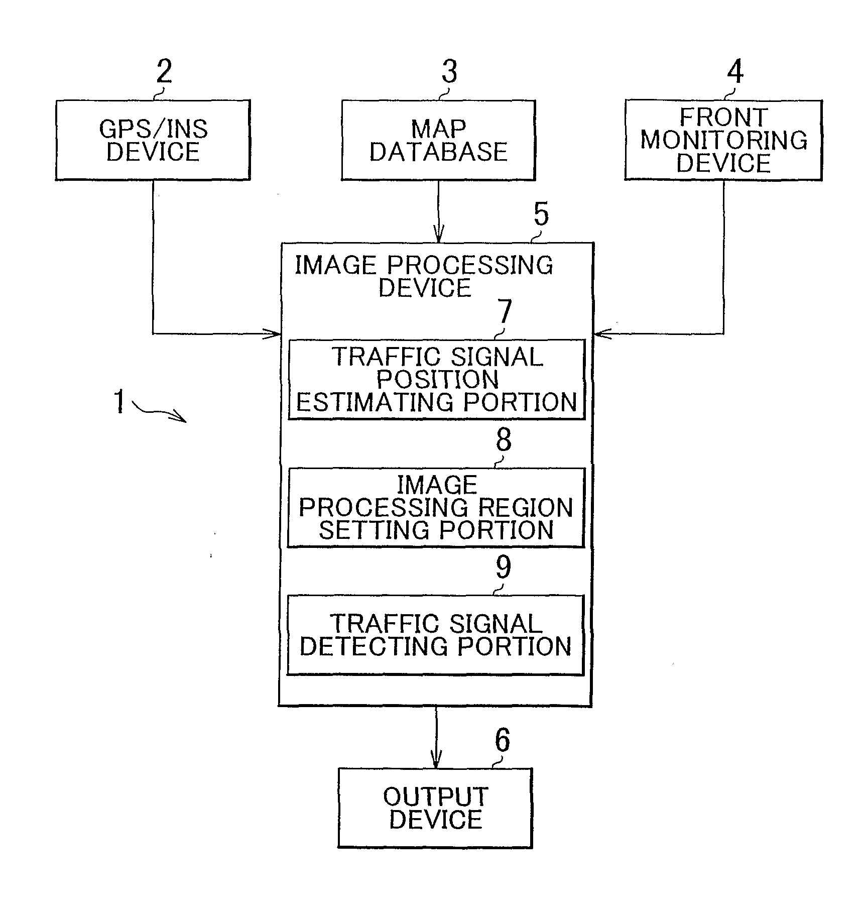
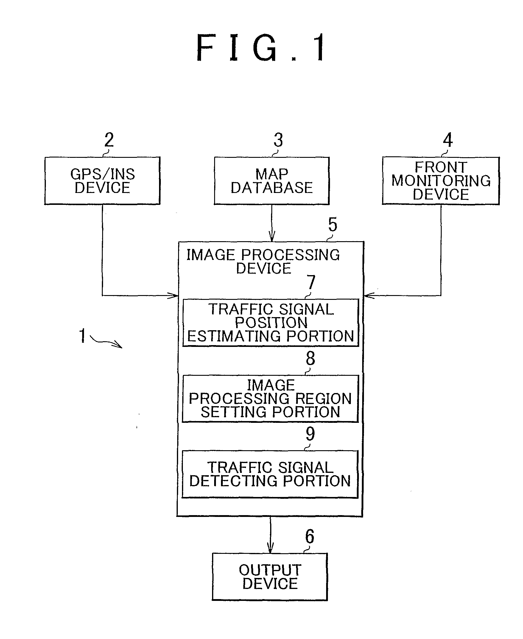
[0042]FIG. 1 illustrates an example of the overall configuration of an image processing system according to the first exemplary embodiment. The image processing system includes a GPS (Global Positioning System) / INS (Inertial Navigation System) device 2, a map database 3, a front monitoring device 4, an image processing device 5, and an output device 6. The image processing device 5 includes a traffic signal position estimating portion 7, an image processing region setting portion 8, and a traffic signal detecting portion 9.

[0043]The GPS / INS device 2 receives navigation messages from GPS satellites and determines the coordinate of the vehicle based on the received messages, and the GPS / INS device 2 accurately estimates the position of the vehicle using an autonomous navigation method.

[0044]More specifically, the GPS / INS device 2 determines the position of the vehicle using electric waves that the GPS / INS device 2 receives from the GPS satellites. That is, the distance between the veh...

second exemplary embodiment

[0131]According to an image processing system of the second exemplary embodiment, the true coordinate of a traffic signal is calculated through predetermined calculations using, as an initial value, the position of the traffic signal which is estimated by the traffic signal position estimating portion 7 on the road map, and the calculated true coordinate of the traffic signal is recorded in a database. Note that the position of a traffic signal will be referred as “the coordinate of a traffic signal” where appropriate and the coordinate of each traffic signal is defined by the latitude, longitude, and altitude. According to this image processing system, because the true coordinate of a traffic signal is recorded in the database, the speed of image processing increases.

[0132]FIG. 13 shows one example of the configuration of the image processing system according to the second exemplary embodiment. In FIG. 13, the components that are the same as those in FIG. 1 will be designated by th...


PUM


Abstract

An image processing system is provided, which includes: a front monitoring device that obtains an image of a view ahead of a vehicle; a vehicle position detecting device that detects the position and orientation of the vehicle; a map database that stores road maps; a traffic indicator position estimating portion that estimates the position of a traffic indicator (23) based on the shape of a road ahead of the vehicle that has been extracted from the map database, according to the position of the vehicle that has been detected by the vehicle position detecting device; an image processing region setting portion that sets an image processing region within the image obtained by the front monitoring device based on the position of the traffic indicator that has been estimated by the traffic indicator position estimating portion; and a traffic indicator detecting portion that detects the traffic indicator from the image processing region.

Description

BACKGROUND OF THE INVENTION[0001]1. Field of the Invention[0002]The invention relates to an image processing system and method for detecting a traffic indicator ahead of a vehicle.[0003]2. Description of the Related Art[0004]With improvement of the performance of on-vehicle cameras and evolution of information processing technologies, technologies have been proposed in which a vehicle detects the conditions around the vehicle and encourages the driver to perform an emergency operation to avoid a danger as needed, and performs an automatic vehicle control that, for example, brakes the vehicle (for example, see JP-A-10-177699).[0005]In the technology described in JP-A-10-177699, during route guidance for the driver of a vehicle, a traffic indicator, such as a traffic signal, is detected from the data of images captured in the traveling direction of the vehicle when the vehicle is approaching a diverging point in the directed route, and the route guidance is then performed for the driv...

Claims


Application Information

Patent Timeline
Patent Type & Authority Applications(United States)
IPC IPC(8): G08G1/00H04N7/18
CPCG08G1/096716G06K9/00818G06K9/00825G08G1/096791G08G1/09623G06V20/582G06V20/584
Inventor ONOME, HIROHISAWATANABE, KOJI
Owner TOYOTA JIDOSHA KK
Learn More