
Medium feeding device and recording apparatus

a feeding device and recording device technology, applied in the direction of registering devices, thin material processing, article separation, etc., can solve the problems of skew newly occurring, and inability to remove the difference between the left and right deflection, so as to stabilize the attitude of the medium

Active Publication Date: 2009-12-03
SEIKO EPSON CORP
View PDF2 Cites 15 Cited by
  • Summary
  • Abstract
  • Description
  • Claims
  • Application Information

AI Technical Summary

Benefits of technology

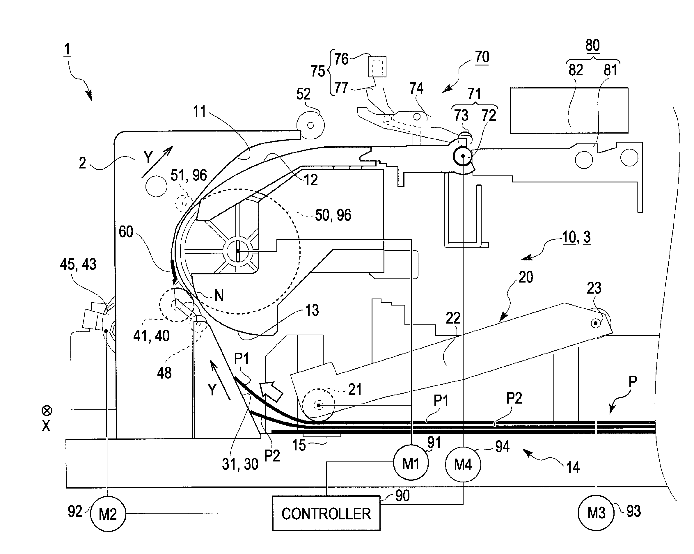
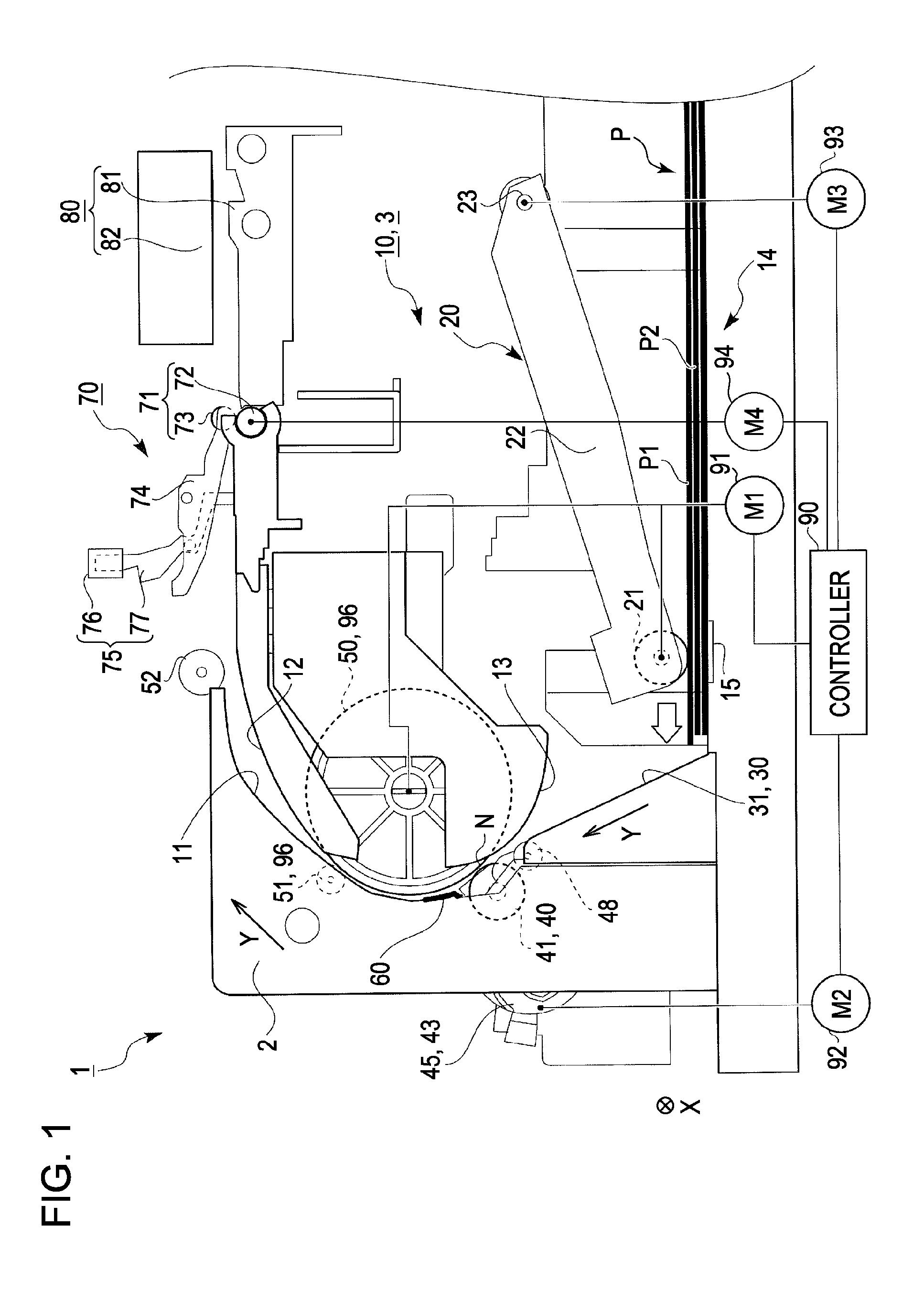
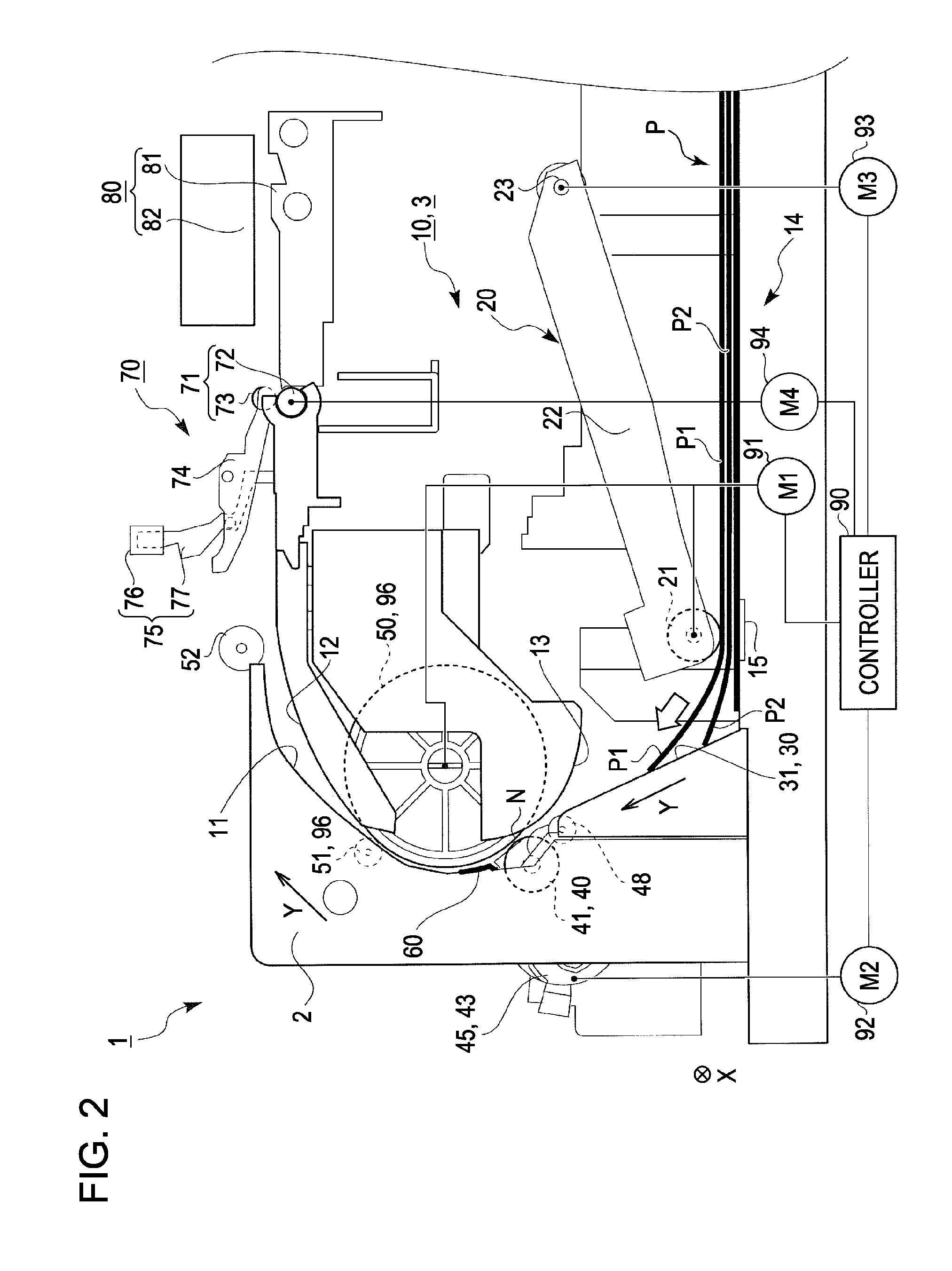
[0016]An advantage of some aspects of the invention is to provide a medium feeding device that can stabilize the attitude of a medium being transported and transport the medium, and a recording apparatus including the medium feeding device.

Problems solved by technology

As a result, there is a concern that skew newly occurs while the paper sheet is transported after the skew correction.
In particular, if the guiding path of the paper sheet between picking-up and the transport roller pair 208 is curved in side view, a trouble is apt to be generated in the case of a paper sheet of which the size is A3 or more.
That is, if there is difference between the left and right deflections, there is a concern that it may not be possible to remove the difference between the left and right deflections even if the feed driven roller is separated from the feed driving roller.

Method used


Image

  • Medium feeding device and recording apparatus
  • Medium feeding device and recording apparatus
  • Medium feeding device and recording apparatus

Examples


embodiment 1

Another Embodiment 1

[0158]FIG. 14 is a side view illustrating a discharge state at the time of skew correction in another embodiment 1.

[0159]As shown in FIG. 14, in a printer 100 according to another embodiment 1, attitude detectors 101a and 101b that detect the attitude of a deflected paper sheet P1 are provided between a feed roller pair 96 and a transport roller pair 71 in a feed direction Y. Specifically, the attitude detectors are provided to detect whether the deflection of the paper sheet exceeds predetermined deflection. Further, a pair of attitude detectors 101a and 101b is provided in a width direction X. Specifically, the pair of attitude detectors is provided at positions that face one and the other ends of the paper sheet P1 in the width direction X.

[0160]The attitude detectors 101a and 101b include levers 102a and 102b and detection sensors 104a and 104b, respectively. The levers 102a and 102b are provided to swing about lever shafts 103a and 103b, respectively. Furthe...

embodiment 2

Another Embodiment 2

[0173]FIG. 15 is a side view illustrating that an intermediate driving roller of another embodiment 2 is rotationally driven in a normal direction. FIG. 16 is a side view illustrating that the intermediate driving roller of another embodiment 2 is rotationally driven in a reverse direction.

[0174]As shown in FIGS. 15 and 16, a printer 110 according to another embodiment 2 includes a planetary gear mechanism 111. Further, an intermediate driving roller 116 is formed so as to approach or be separated from a second assist roller 117 by the planetary gear mechanism 111.

[0175]Specifically, the planetary gear mechanism 111 includes a first gear 112, a second gear 113, a third gear 114, and a gear holder 115. The first gear 112 is rotated by the power of a feeding motor 91. Further, the second gear 113 is rotatably held by the gear holder 115, is in contact with the first gear 112, and is rotated by power transmitted from the first gear 112. Furthermore, the third gear 1...


PUM

PropertyMeasurementUnit
timeaaaaaaaaaa
widthaaaaaaaaaa
poweraaaaaaaaaa

Abstract

A medium feeding device includes a feed roller pair, a transport roller, a medium guiding path section, and a controller. The feed roller pair includes a feed driving roller driven by power and a feed driven roller to be rotationally driven, and feeds a medium to be fed toward the downstream side in a feed direction. The feed driving roller and the feed driven roller are separated from each other. The transport roller pair transports the medium, which is fed by the feed roller pair, toward the downstream side in the feed direction. The transport roller pair includes a transport driving roller that is disposed on the downstream side of the feed roller pair in the feed direction and is driven by power and a transport driven roller that is rotationally driven.

Description

BACKGROUND[0001]1. Technical Field[0002]The present invention relates to a medium feeding device and a recording apparatus including the medium feeding device. The medium feeding device includes a feed roller pair, a transport roller pair, and a medium guiding path section. The feed roller pair includes a feed driving roller driven by power and a feed driven roller to be rotationally driven, and feeds a medium to be fed toward the downstream side in a feed direction. The transport roller pair transports the medium, which is fed by the feed roller pair, toward the downstream side in the feed direction, and includes a transport driving roller that is disposed on the downstream side of the feed roller pair in the feed direction and is driven by power and a transport driven roller that is rotationally driven. The medium guiding path section guides the fed medium up to the transport roller pair.[0003]In the invention, examples of the recording apparatus include an ink jet printer, a wire...

Claims


Application Information

Patent Timeline
Patent Type & Authority Applications(United States)
IPC IPC(8): B65H5/06
CPCB65H3/0684B65H5/062B65H5/068B65H2404/1531B65H2301/3122B65H2404/1115B65H2404/144B65H9/008
Inventor YANAGISHITA, KENJI
Owner SEIKO EPSON CORP
Learn More