
Method and apparatus for preventing catastrophic contact failure in ultra high temperature piezoresistive sensors and transducers

a technology of piezoresistive sensors and transducers, applied in the direction of fluid pressure measurement, conductors, instruments, etc., can solve the problems of destroying contact, dissolving platinum and destroying contact, and deemed unsuitable for these operations, and free glass frits are not suitable for operation

Inactive Publication Date: 2009-12-03
KULITE SEMICON PRODS
View PDF4 Cites 43 Cited by
  • Summary
  • Abstract
  • Description
  • Claims
  • Application Information

AI Technical Summary

Benefits of technology

The patent text describes a method to prevent failure of electrical contacts in a silicon transducer with piezoresistive sensors. The method involves replacing the lead glass frit with a non-lead glass frit to prevent interaction between the lead glass and the platinum contacts at high temperatures. The technical effect of this method is to improve the reliability and durability of the silicon transducer.

Problems solved by technology

The devices resulting from the methods described in the aforementioned patents permitted the fabrication of structures which were suitable for use up to slightly over 600° C. However, it was found that at approximately 620° C., or greater, there was a catastrophic failure in the electrical contacts to the piezoresistive sensor network.
However, it was discovered that at temperatures greater than 620° C. lead could interact with platinum forming a liquidous, thereby dissolving the platinum and destroying the contact.
However, one reason such lead free glass frits were deemed unsuitable for these operations was because the original glass frit melting and softening points were considerably higher than the lead containing glass frits.
When using such a lead-free frit, the contact glass (as described in the aforementioned patents), namely borosilicate glass, would not withstand the new firing temperatures required for the firing of the lead-free frits.

Method used


Image

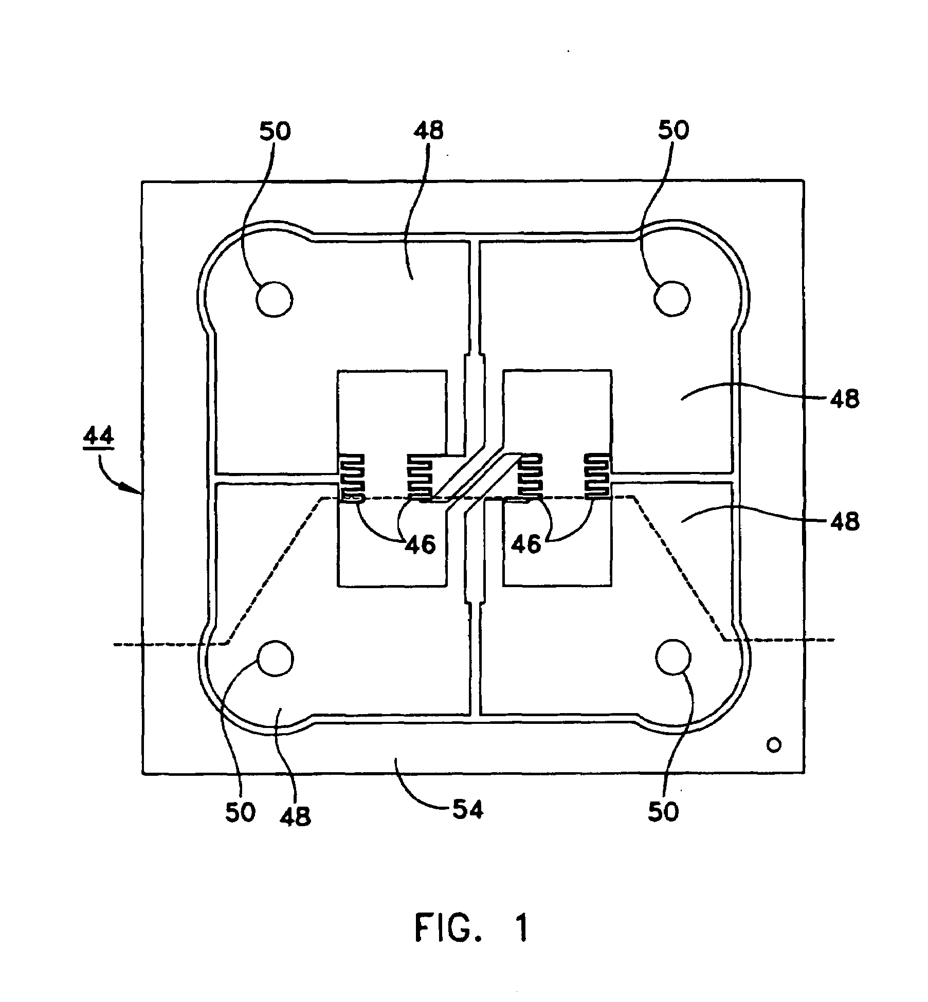
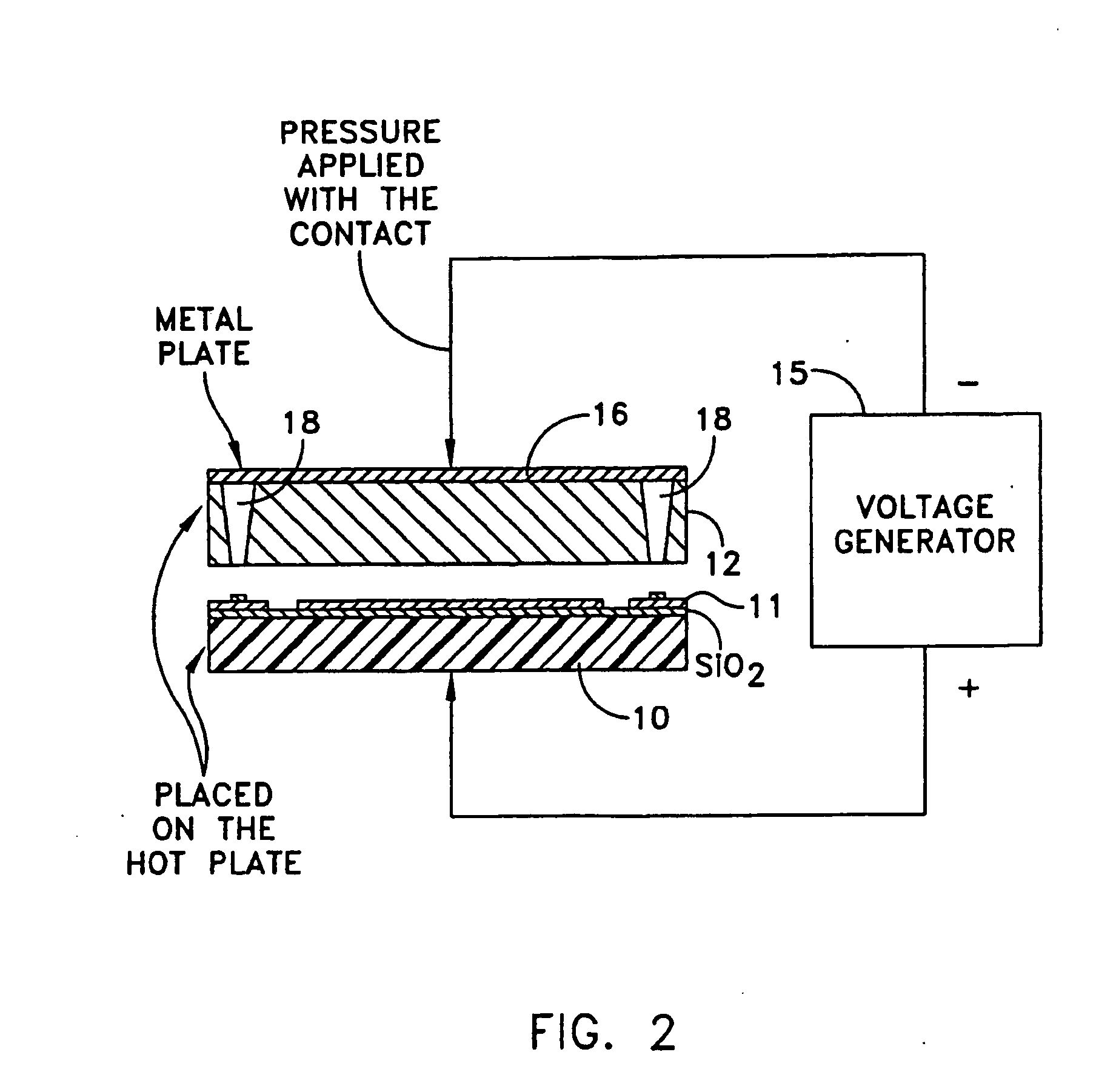
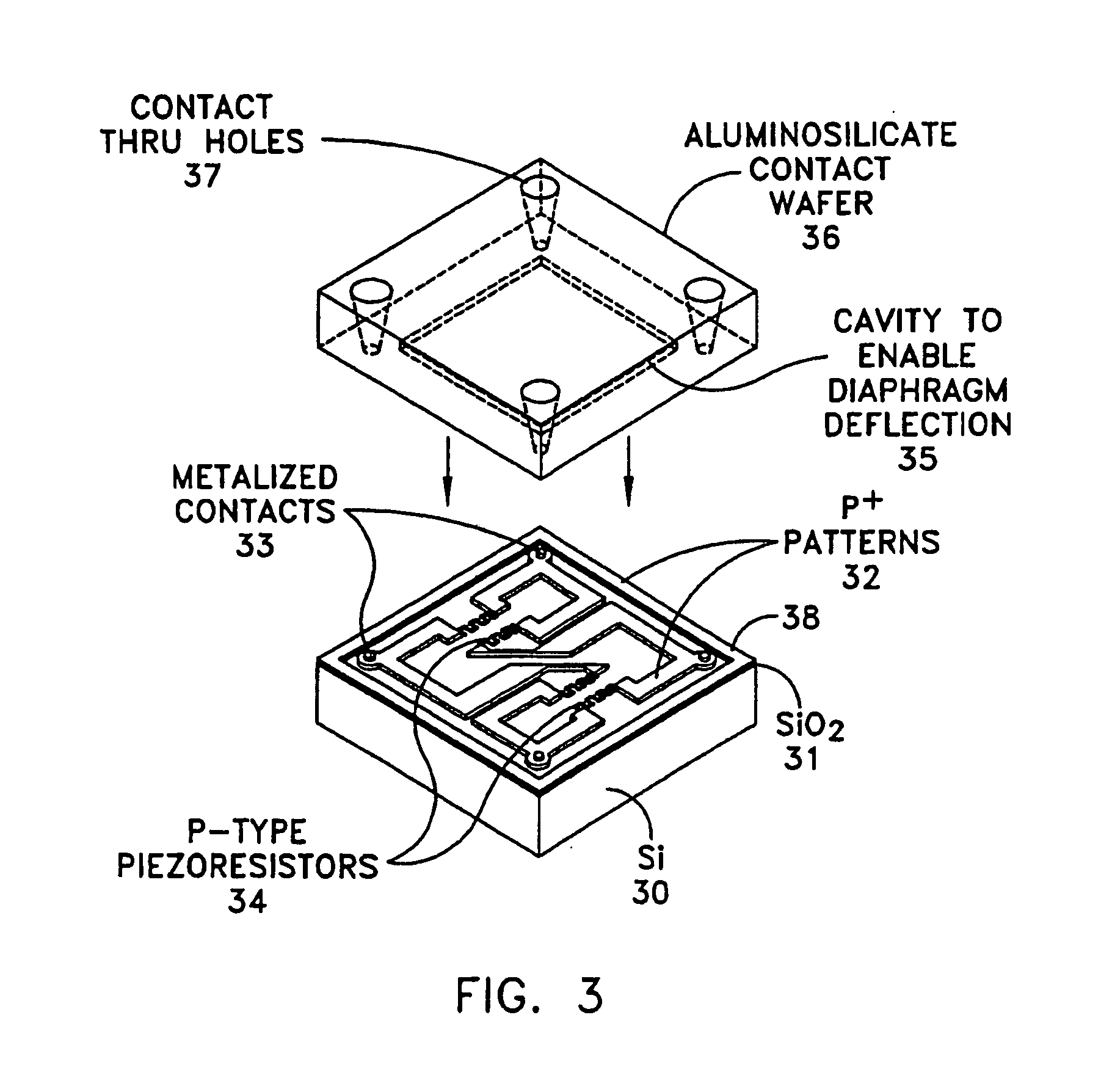
  • Method and apparatus for preventing catastrophic contact failure in ultra high temperature piezoresistive sensors and transducers
  • Method and apparatus for preventing catastrophic contact failure in ultra high temperature piezoresistive sensors and transducers
  • Method and apparatus for preventing catastrophic contact failure in ultra high temperature piezoresistive sensors and transducers

Examples


Embodiment Construction

[0009]As described herein, the use of lead-free glass frits in a high temperature SOI leadless sensor gave rise to certain unanticipated advantages. Not only was it able to withstand much higher temperatures, but its expansion coefficient was much more closely matched to that of silicon (35 PPM / °C.) and the borosilicate glass versus (85 PPM / °C.) for the lead-bearing. In contrast, when the lead-bearing frit was used to fill the holes in the contact glass, the difference in expansion coefficients between the lead-bearing frit and the silicon borosilicate structure gave rise to considerable elastic stress which degraded the device performance.

[0010]Furthermore, it was found that in order to use the high temperature, low expansion lead-free frit, a different contact glass was required capable of withstanding the higher melting point of the lead-free glass-metal frit. It was discovered that glasses such as aluminum oxide-zinc oxide-zinc oxide-borosilicate glasses, not only had a higher m...


PUM

PropertyMeasurementUnit
temperatureaaaaaaaaaa
voltageaaaaaaaaaa
voltageaaaaaaaaaa

Abstract

A method to prevent the catastrophic failure of electrical contacts of silicon piezoresistive transducers located on a silicon wafer at temperatures above 600° C. comprising the steps of using a lead-free glass frit to surround the contacts and bonding the sensor wafer to a glass wafer employing a lead-free glass and utilizing a modified electrostatic bonding technique to join the silicon wafer to the lead-free glass wafer to form a high temperature SOI device.

Description

FIELD OF THE INVENTION[0001]This invention relates to silicon on insulator leadless ultra high temperature pressure transducers and more particularly to a method and apparatus for preventing catastrophic failure of contacts in such transducer.BACKGROUND OF THE INVENTION[0002]Some years ago, Kulite Semiconductor Products, Inc. (Kulite) had received patents on the method of construction of high temperature silicon on oxide leadless pressure transducers. In our previous art, the method for making the silicon-on-insulator sensor is described in U.S. Pat. No. 5,286,671 entitled “Fusion Bonding Technique for Use in Fabricating Semiconductor Devices” issued on Feb. 15, 1994 to A. D. Kurtz et al. and assigned to Kulite the assignee herein, and the method for making the leadless high temperature transducer structure is described in U.S. Pat. No. 5,955,771 entitled “Sensor for Use in High Vibrational Application and methods for Fabricating Same” issued on Sep. 21, 1999 to A. D. Kurtz et al. a...

Claims


Application Information

Patent Timeline
Patent Type & Authority Applications(United States)
IPC IPC(8): H01B1/16C03C8/04
CPCC03C3/062C03C3/064C03C3/083C03C3/085G01L19/0069C03C27/044G01L9/0042G01L9/0055C03C3/091
Inventor KURTZ, ANTHONY D.NED, ALEXANDER A.
Owner KULITE SEMICON PRODS
Learn More