
Impact Resistant Core

a core and impact resistance technology, applied in the direction of synthetic resin layered products, fuselage bulkheads, textiles and paper, etc., can solve the problems of reducing the performance characteristics of sandwich composite structures, requiring relatively frequent inspection and replacement of components, and reducing the optimal resistance of sandwich composite structures to damag

Active Publication Date: 2009-11-19
THE BOEING CO
View PDF28 Cites 5 Cited by
  • Summary
  • Abstract
  • Description
  • Claims
  • Application Information

AI Technical Summary

Benefits of technology

The patent text describes methods for making impact resistant cores for use in aircraft components. The cores are made from a honeycomb structure made of poly p-phenylene-2,6-benzobisoxazole fibers and a binding resin. The text also describes a composite sandwich structure that includes a stiffening element and a laminate face sheet, as well as an aircraft component made of a stiffening element and laminate face sheet. The methods involve wetting the fibers with a resin and shaping them to form a corrugation, which is then bonded to make a honeycomb. The text also describes a method of making a structural core by bonding two or more fiber sheets using an adhesive and expanding them to make cells between them, which is then applied with a resin and cured. The technical effects of the patent text are improved impact resistance and reduced weight of aircraft components, making them more durable and reliable.

Problems solved by technology

However, there can be trade-offs with using sandwich composite structures rather than solid materials.
For example, sandwich composite structures can have reduced material performance characteristics.
Additionally, such sandwich composite structures may have less than optimal resistance to damage by impact with foreign objects.
Hence, when aircraft components are made using sandwich composite structures, the components may require relatively frequent inspection and replacement.
Additionally, the illustrations are merely representational and may not be drawn to scale.

Method used


Image

  • Impact Resistant Core
  • Impact Resistant Core
  • Impact Resistant Core

Examples


Embodiment Construction

[0015]The features, functions, and advantages that have been discussed can be achieved independently in various embodiments disclosed herein or may be combined in yet other embodiments further details of which can be seen with reference to the following description and drawings.

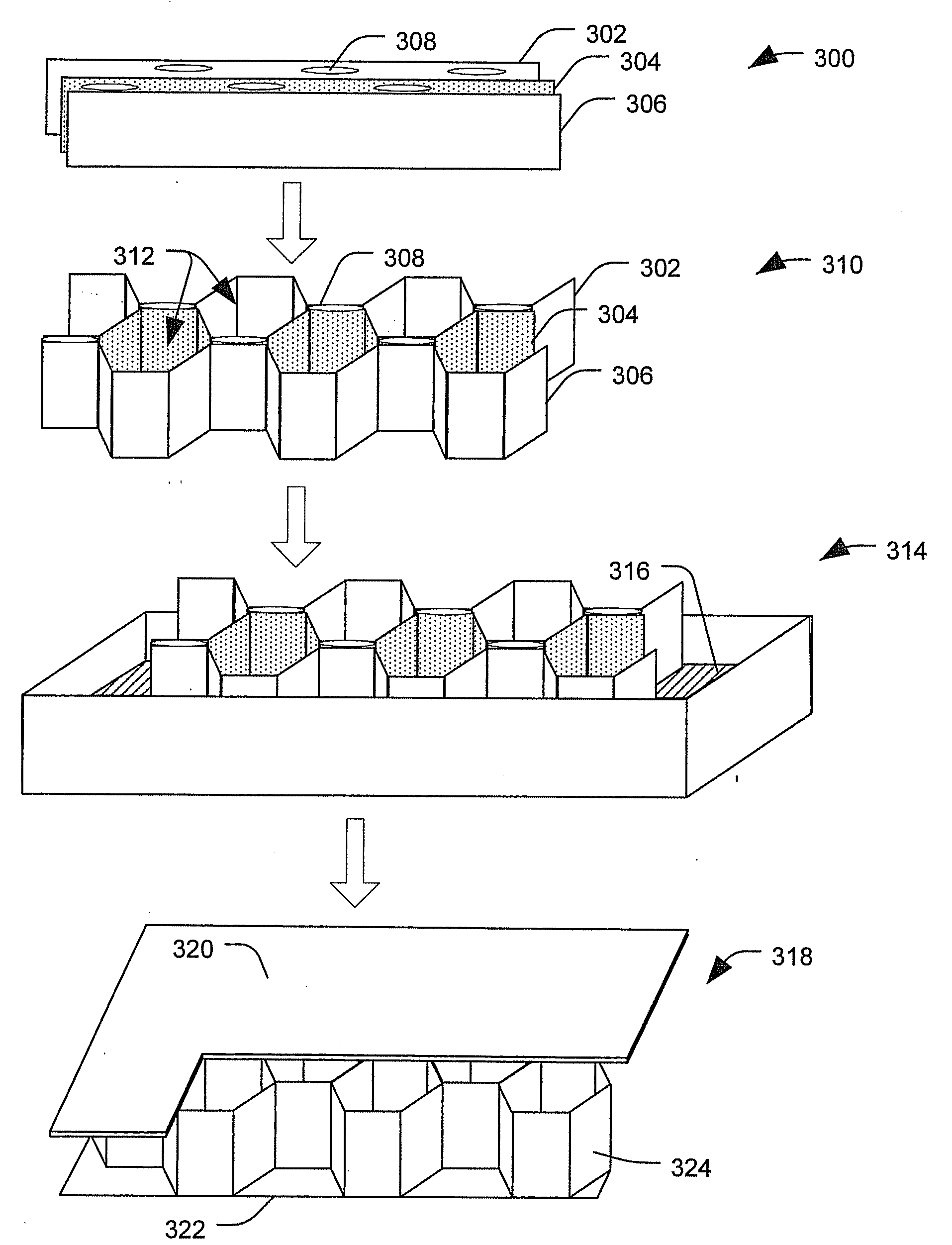
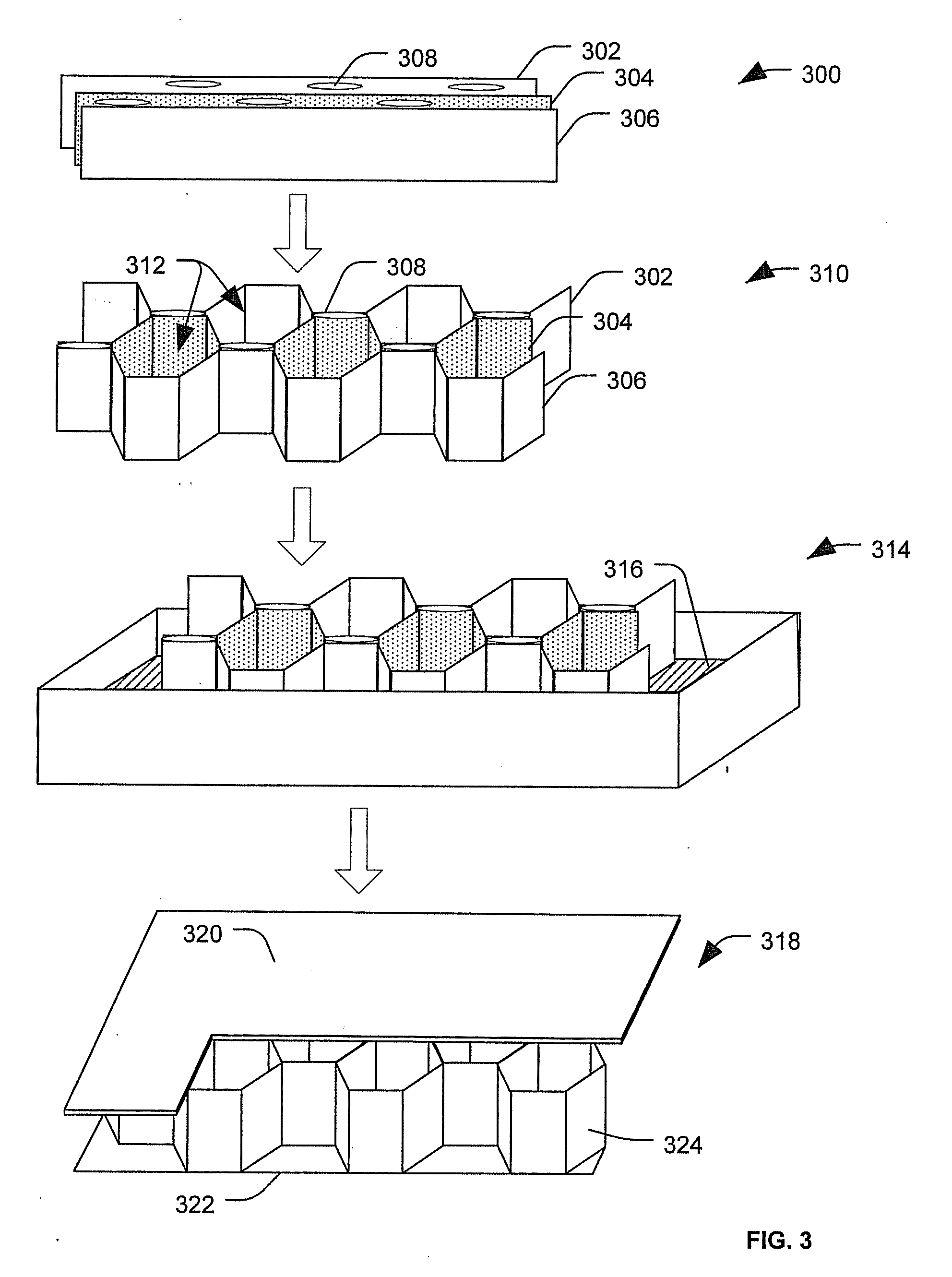
[0016]By way of introduction, in a particular embodiment, an impact resistant core can be made by shaping a plurality of fibers into a desired configuration (such as a honeycomb structure) and binding the fibers together using a resin. Impact resistant cores made in this manner can be used as stiffening elements in sandwich composite structures to make parts that are lightweight and durable. For example, the impact resistant cores can be used to make various aircraft components. The sandwich composite structures can include one or more laminate face sheets coupled to the core. When the impact resistant core is to be used to make aircraft components, the resin and the fibers may be selected to reduce thermal e...


PUM

PropertyMeasurementUnit
impact energyaaaaaaaaaa
weightaaaaaaaaaa
stiffnessaaaaaaaaaa

Abstract

Impact resistant cores and methods of manufacturing such impact resistant cores are provided. Additionally, components made using the impact resistant cores are provided. A particular impact resistant core includes a composite structure of at least one non-woven sheet including poly p-phenylene-2,6-benzobisoxazole fiber and a binding resin.

Description

FIELD[0001]The present disclosure is generally related to impact resistant cores.BACKGROUND[0002]Composite structures that include a core sandwiched between face sheets are used for many purposes. Often the core includes cells or air pockets to reduce the weight of the composite structure as compared to a similar structure made from solid materials (i.e., materials without cells or air pockets). The reduced weight of these composite structures has led the aircraft industry to use such composite structures to reduce the weight of aircraft components.[0003]In sandwich structures the core can serve several purposes, such as providing stiffness to the structure, insulating the structure, providing thickness to the structure to achieve desired dimensional characteristics, to offset the face sheets, to support and stabilize the face sheets, etc. However, there can be trade-offs with using sandwich composite structures rather than solid materials. For example, sandwich composite structures...

Claims


Application Information

Patent Timeline
Patent Type & Authority Applications(United States)
IPC IPC(8): B32B3/12D04H13/00C08G83/00B32B37/00
CPCB29C53/24Y10T156/1003B32B3/12B32B5/26B32B5/28B32B9/00B32B27/02B32B27/04B32B27/12B32B27/38B32B27/42B32B37/146B32B2305/024C08G73/22C08J5/046C08J2361/06Y10T428/24149B29D99/0089B32B5/022B32B5/08B32B5/22B32B7/12B32B2260/021B32B2260/046B32B2262/02B32B2262/0269B32B2262/14B32B2307/558B32B2307/718B32B2605/18Y10T442/2623Y10T442/60
Inventor GERKEN, NOEL T.PATZ, NICK
Owner THE BOEING CO
Learn More