
Multi-input power-switching circuit

a power-switching circuit and multi-input technology, applied in emergency power supply arrangements, a dc network circuit arrangements, etc., can solve problems such as one power source, electronic device shutdown, booster unit overload, etc., to prolong the operation of electronic devices, stable driving power, and higher voltage input power

Inactive Publication Date: 2009-11-19
ZIPPY TECH
View PDF9 Cites 9 Cited by
  • Summary
  • Abstract
  • Description
  • Claims
  • Application Information

AI Technical Summary

Benefits of technology

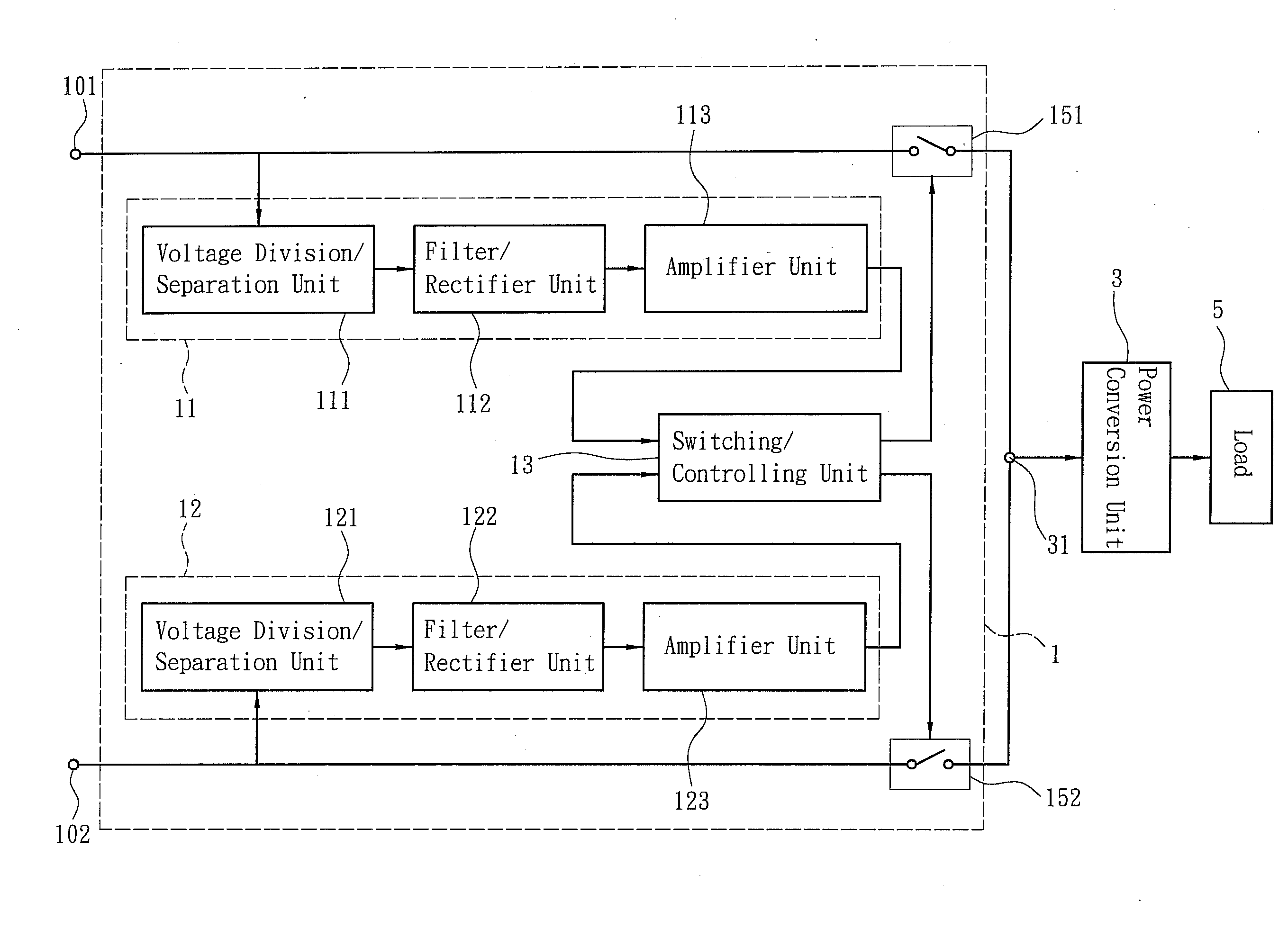
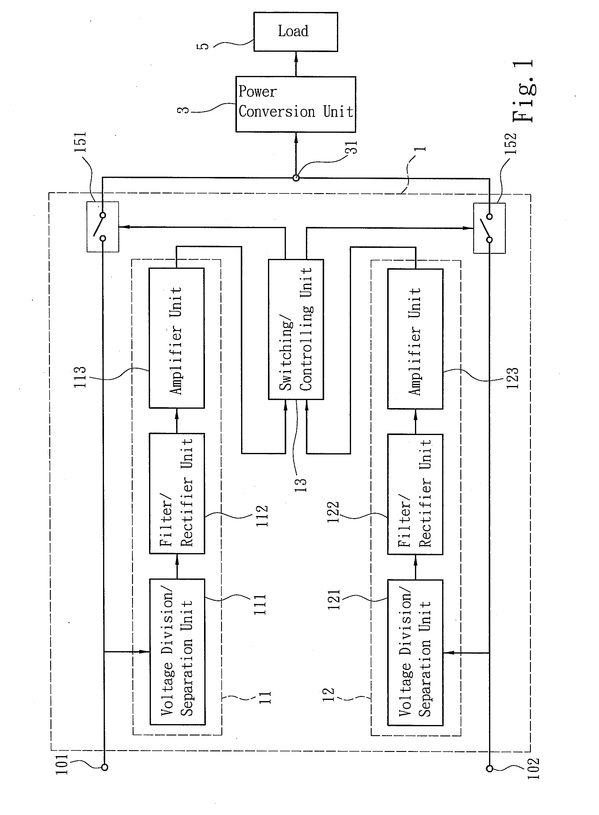
"The present invention provides a multi-input circuit architecture that can detect and evaluate the voltages of several power sources and select the highest-voltage power source as the input power to guarantee a stable driving power. This solves the problem of conventional power supply devices having only one power source and can prolong the operation of electronic devices for a longer time. The multi-input power-switching circuit of the present invention connects with more than one power source and includes a switching / controlling unit that can determine which power input terminal has a higher voltage level and generate a turn-on signal to turn on the switch connected with the power input terminal having a higher voltage level. This ensures that the power conversion unit can acquire a higher voltage input power and provide a stable driving power for a load."

Problems solved by technology

However, the conventional design has only one power source.
When the commercial power or the source power supply device fails, the electronic device will shut down.
When the input power drops, the booster unit of the power supply device will be overburdened and thus damaged.
Therefore, the UPS cannot actively switch between different power sources but can only passively prolong the operation of the electronic device for a while.
However, the prior arts need three power supply modules and have the disadvantages of bulkiness and high price, which limit their applications.
In fact, the prior art cannot really discriminate the levels of the two power sources.

Method used


Image

  • Multi-input power-switching circuit
  • Multi-input power-switching circuit
  • Multi-input power-switching circuit

Examples


Embodiment Construction

[0008]Below, the technical contents of the present invention will be described in detail in cooperation with the drawings.

[0009]The present invention proposes a multi-input power-switching circuit, which acquires more than one power sources and selects one of the power sources to connect with a power conversion unit. The multi-input power-switching circuit of the present invention comprises: more than one power input terminal, more than one detection / evaluation circuit, and a switching / controlling unit. Refer to FIG. 1 a block diagram showing the circuit of an embodiment of the present invention. The multi-input power-switching circuit 1 has two power input terminals 101 and 102 respectively receiving different input powers from different power sources. Two switches 151 and 152 are respectively arranged in the paths via which the different input powers are transferred to a power conversion unit 3. One end of the switch 151 / 152 is coupled to the power input terminal 101 / 102, and the ...


PUM


Abstract

The present invention discloses a multi-input power-switching circuit, which comprises: more than one power input terminal, more than one detection / evaluation circuit, and a switching / controlling unit. A switch is arranged in the path via which the input power is received by the power input terminal and then transferred to the power conversion unit. Each detection / evaluation circuit receives a partial voltage signal from one input power and generates a detection signal according to the partial voltage signal. The switching / controlling unit receives the detection signals from the detection / evaluation circuits, determines which power input terminal has a higher voltage level according to the detection signals, and generates a turn-on signal to turn on the switch connected with the power input terminal having a higher voltage level. Thereby, the power conversion unit can acquire a higher voltage input power and provide a stable driving power for a load.

Description

FIELD OF THE INVENTION[0001]The present invention relates to a multi-input power-switching circuit, which detects and evaluates the qualities of several power sources and then selects one of the power sources as the input power.BACKGROUND OF THE INVENTION[0002]An electronic device needs a stable power supply; therefore, the power supply device thereof has to provide a stable power supply for the electronic device. Generally, a power supply device is coupled to a power source to acquire an input power, and the power conversion unit of the power supply device converts the input power into a driving power and sends the driving power to loads. However, the conventional design has only one power source. The power source may be a commercial power or another power supply device. When the commercial power or the source power supply device fails, the electronic device will shut down. When the input power drops, the booster unit of the power supply device will be overburdened and thus damaged...

Claims


Application Information

Patent Timeline
Patent Type & Authority Applications(United States)
IPC IPC(8): H02J4/00
CPCH02J9/061H02J3/005H02J3/007
Inventor HUANG, YUNG-HSIN
Owner ZIPPY TECH
Learn More