
Integrated aircraft structure in composite material

Active Publication Date: 2009-11-19
AIRBUS OPERATIONS SL
View PDF7 Cites 54 Cited by
  • Summary
  • Abstract
  • Description
  • Claims
  • Application Information

AI Technical Summary

Benefits of technology

[0016]According to the invention, a fuselage section is formed starting from individual U-section elements that assume various structural functions, forming part of the frame and of the skin at the same time. On joining these U-shaped elements with the basic skin and the stringers before the final phase of co-curing, the required complete integrated structure is obtained. This means having all the advantages that an integrated structure provides, such as cost saving in manufacture, since the composite material requires a fairly expensive curing process, and owing to integration the number of curing cycles and hence the costs are reduced, and at the same time it provides more uniform transmission of loads between the elements that make up the structure.
[0017]Thus, the aircraft fuselage structure according to the invention will integrate the skin with stringers and feet of the frames to benefit from the assembly advantages from using floating frames, as well as the simplification that results from manufacturing of said frames, without requiring a larger number of pieces and therefore without penalizing the number of joints.
[0018]Accordingly, the present invention relates, on the one hand, to an integrated aircraft fuselage structure with the following characteristics: the structure comprises a skin, stringers and frame feet, in such a way that the whole is integrated and a complete fuselage structure is obtained in a single piece, without the need to use rivets or joints; the frame feet of the aforesaid structure are formed from continuous U-shaped elements, which fulfil a dual structural function, acting both as skin and as T-shaped frame feet proper, of said fuselage structure; the frame feet of the invention, being integrated, do not need to be joined by rivets or bonded joints to the structure of the fuselage, thereby reducing the number of joints, thus avoiding the possibility of debonding and reducing the assembly time.

Problems solved by technology

The problem posed by these known complete frames is that it is necessary to use complicated and expensive tooling to achieve the assembly tolerances required to enable said frames to be joined to the skin, taking into account the precise aerodynamic and structural requirements.
However, this known solution of floating frames has the drawback of increasing the number of parts, and therefore the number of joints required.
In the two cases already known, complete frames and floating frames, different assembly stations are needed and a large quantity of fasteners (basically rivets), which involves weight penalties, high costs of production and assembly, and the need for greater logistic capacity.
The problem caused by this integration resides basically in creating sufficient pressure in all the elements during the process of combined curing.
The problem that arises from this document is that, as it is necessary to carry out the lay-up and forming of many parts, the costs of manufacture are very high, and furthermore, loads are transferred between the various basic structural elements through the bonded interface, and there may be problems of debonding in said joining zones.

Method used


Image

  • Integrated aircraft structure in composite material
  • Integrated aircraft structure in composite material
  • Integrated aircraft structure in composite material

Examples


Embodiment Construction

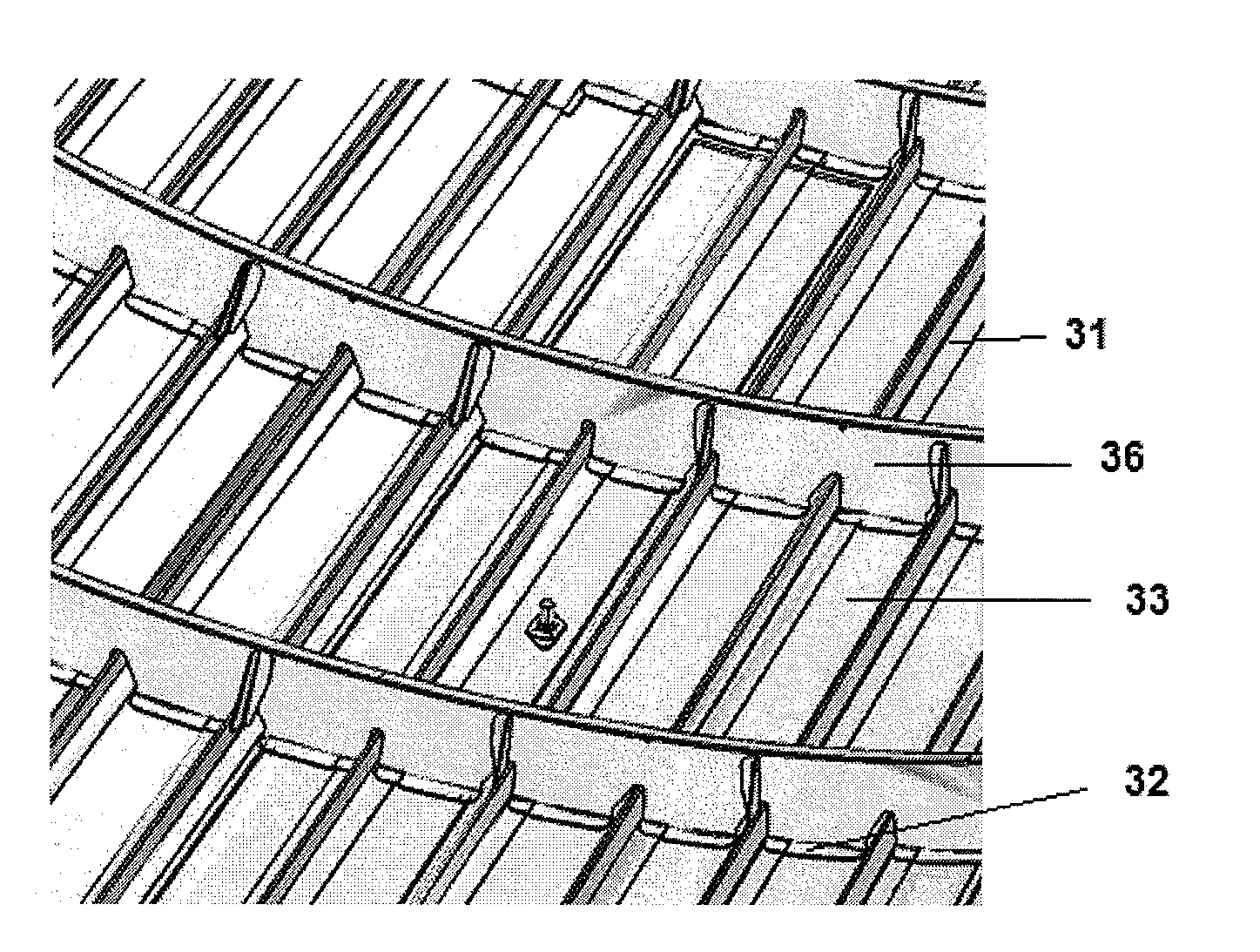
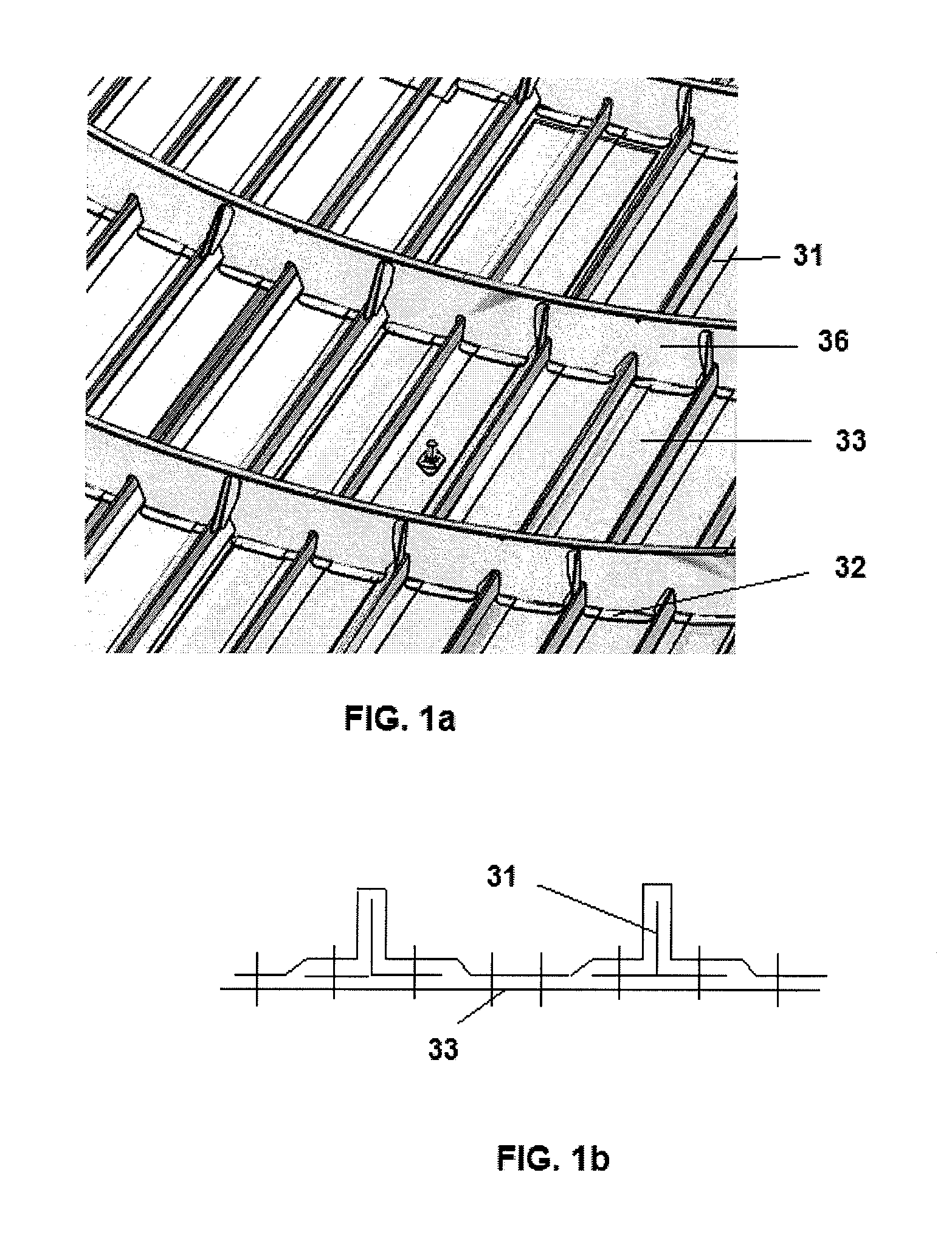
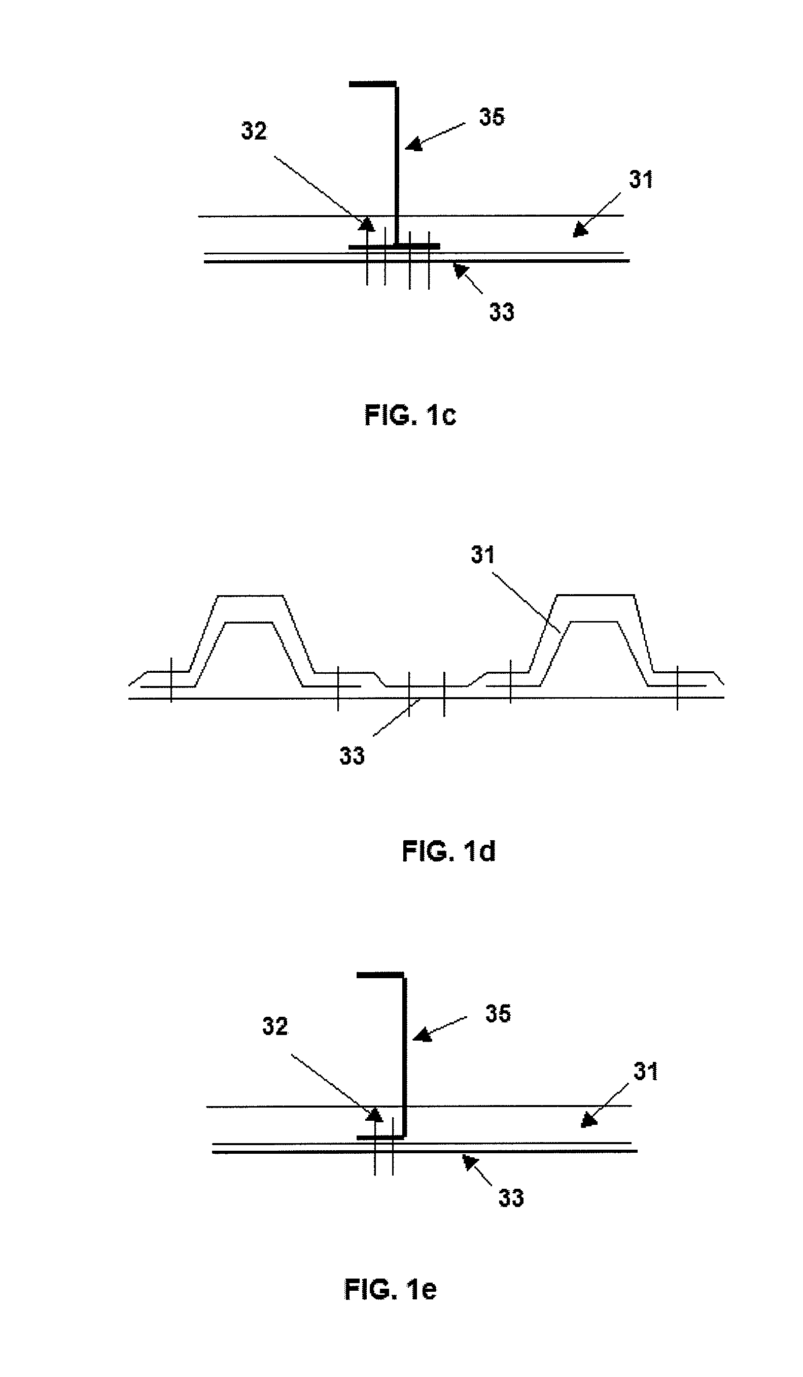
[0042]Aircraft fuselage structures that employ known complete frames comprise frames 36, which in their turn comprise a web 35, frame feet 32, stringers 31 and a skin 33, said feet 32 being riveted to the skin 33. The details of this configuration can be seen in FIGS. 1a-1e.

[0043]On the other hand, aircraft fuselage structures that employ known floating frames comprise, for the frame, two different pieces, a floating frame 46 as such and a foot 42. Moreover, they include a skin 43 to which the feet 42 are joined by rivets, and stringers 41, to which the aforesaid feet 42 are also joined. This structure can be seen in FIGS. 2a-d.

[0044]Thus, the present invention proposes a highly integrated aircraft fuselage structure that comprises a basic skin 3, longitudinal reinforcements or stringers 1 and U-shaped elements 15, in such a way that the integrated structure obtained is more efficient with respect to strength, stiffness and low weight. Moreover, such an integrated configuration me...


PUM

PropertyMeasurementUnit
Temperatureaaaaaaaaaa
Thicknessaaaaaaaaaa

Abstract

Integrated aircraft structure in composite material that comprises a skin and stringers (1), with the skin comprising a skin part (5) and a basic skin (3), and said structure further comprises U-shaped elements (15) each of which comprises in its turn two L-shaped sections (4a+5a and 4b+5b) together with the skin part (5), in such a way that these U-shaped elements (15) fulfil two structural functions in said structure at the same time, acting as frame feet and as skin, providing an integrated fuselage structure without rivets or joints. The invention also relates to a manufacturing process of an integrated aircraft structure in composite material.

Description

FIELD OF THE INVENTION[0001]The present invention relates to an integrated aircraft structure constructed in composite material, in particular for fuselages of aeronautical structures or for similar aircraft structures.BACKGROUND OF THE INVENTION[0002]It is common knowledge that the aeronautical industry requires structures that on the one hand withstand the loads to which they are subjected, meeting high requirements on strength and stiffness, and on the other hand are as light as possible. A consequence of this requirement is the more and more extensive use of composite materials in primary structures, because with appropriate application of said composite materials it is possible in consequence to achieve an important weight saving relative to a design in metallic material.[0003]Integrated structures in particular have proved to be very efficient in this respect. We speak of an integrated structure when the different structural elements are manufactured in one step. This is anoth...

Claims


Application Information

Patent Timeline
IPC IPC(8): B64C1/00B29C65/70
CPCB29D99/0014B29L2031/3082B64C1/061B29C70/30B64C1/12B64C2001/0072Y02T50/433B64C1/064Y02T50/40
Inventor AREVALO RODRIGUEZ, ELENAMUNOZ ROYO, PEDRO LUIS
Owner AIRBUS OPERATIONS SL
Learn More