Strainer with omega type screen

Inactive Publication Date: 2009-11-19
LEE EUI HO
View PDF1 Cites 0 Cited by
  • Summary
  • Abstract
  • Description
  • Claims
  • Application Information

AI Technical Summary

Benefits of technology

[0012]Accordingly, the present invention has been made in view of the above-mentioned problems occurring in the prior arts, and it is an object of the present invention to provide a strainer with an omega-type screen which can prevent erroneous operation, default and occlusion of a fluid machine and a pipeline due to floating and drifting solids, and which can minimize a transformation of a flow channel while maximally providing a screening face. and allow a user to easily disassemble and clean the screen.

Problems solved by technology

However, the conventional strainer has several problems in that the main body itself may contribute to a loss of energy in terms of hydrodynamics, for instance, expansion, reduction, flexure and the like of a pipe body, and in that the screen may cause an obstruction in the entire flow of the fluid since the cross section of the flow channel is inevitably reduced.
Particularly, the conventional strainer has further problems in that it may cause a severe loss of energy in the entire fluid flow when the degree of occlusion of a mesh is increased since an unreasonable process in maintenance, such as disassembly and cleaning of the screen, may cause said maintenance to be neglected; and in that it may cause fatal defects on the fluid machine and the pipeline by arousing unwanted eddy currents and incurring excessive pressure differential between the front and rear points of the strainer.
The screen 200 can be easily disassembled from the U-shaped strainer when a cover 190 located on an upper portion is removed, but it is not easy to clean in that a face where the foreign substances are gathered is not exposed and one end of the screen 200 is closed, and in that it causes a severe transformation of the flow channel during introduction and discharge processes of the fluid into and from the screen 200.
However, the Y-shaped strainer also has several problems in that it does cause a transformation of the flow channel, and in that it is difficult to disassemble and clean the screen 200 since the a face where the foreign substances are gathered and deposited is not exposed like the screen 200 of the U-shaped strainer.

Method used


Image

  • Strainer with omega type screen
  • Strainer with omega type screen
  • Strainer with omega type screen

Examples


Embodiment Construction

[0020]Reference will be now made in detail to the preferred embodiment of the present invention with reference to the attached drawings.

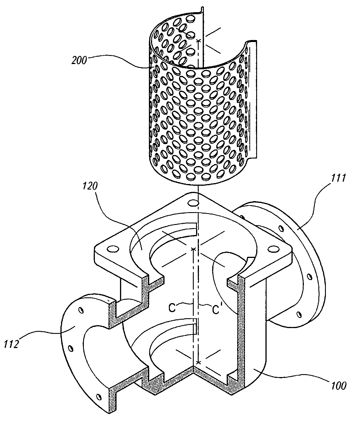
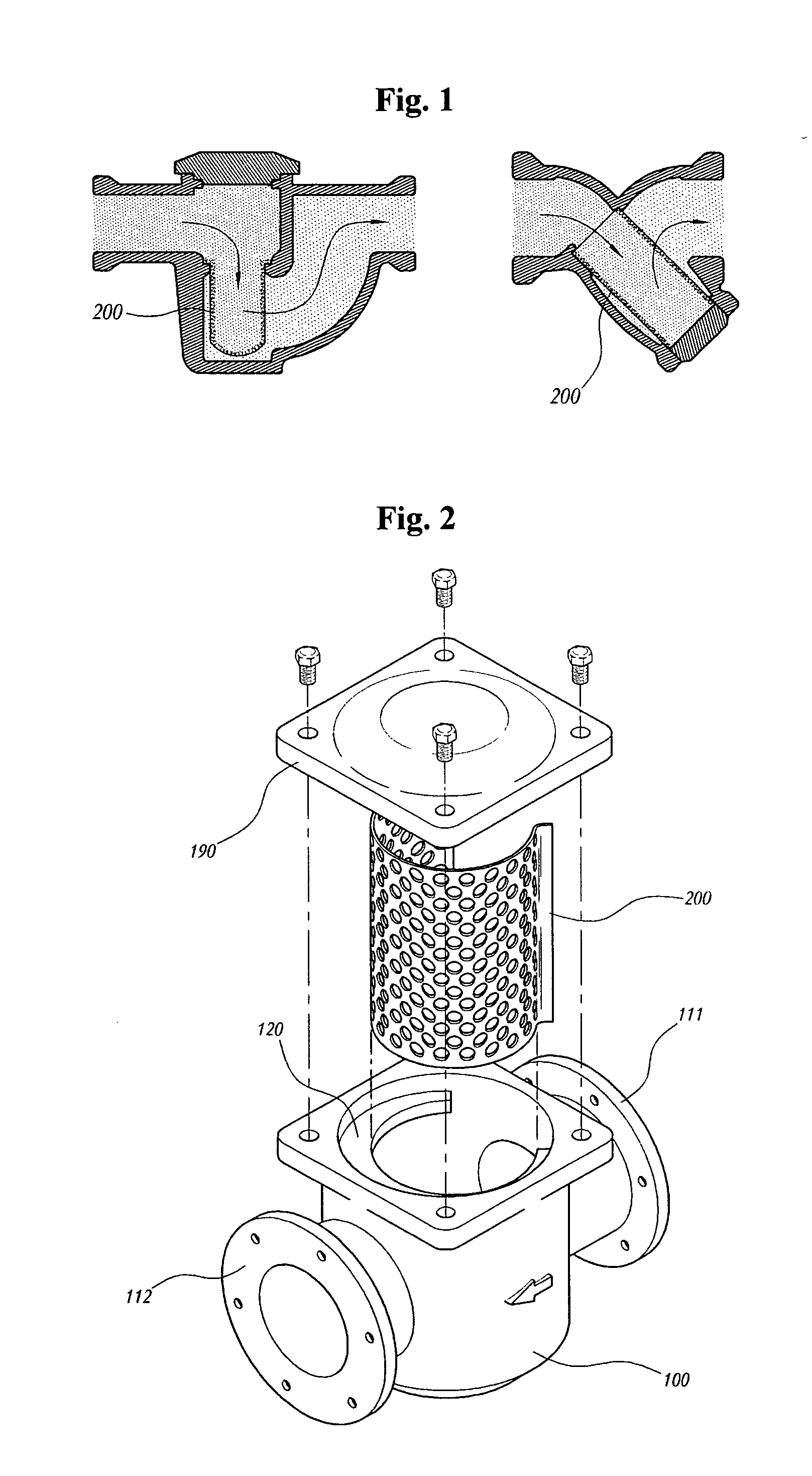
[0021]FIG. 2 is an exploded perspective view showing components of a strainer according to the present invention. As shown in FIG. 2, the strainer includes: a cylindrical main body 100 having an outlet 112 formed on a front face thereof and an inlet 111 formed on a rear face thereof, the main body 100 having a closed lower portion, a screen 200 joined to the inside of the main body 100; and a cover 190 for closing an upper portion of the main body 100.

[0022]While water stops (not shown), such as packings, for ensuring watertightness may be joined to a bottom of the cover 190, an upper end of the main body 100, pipe connection portions of the inlet 111 and the outlet 112, and so on, they are not restricted in claims in detail since those skilled in the art can properly apply them as occasion demands.

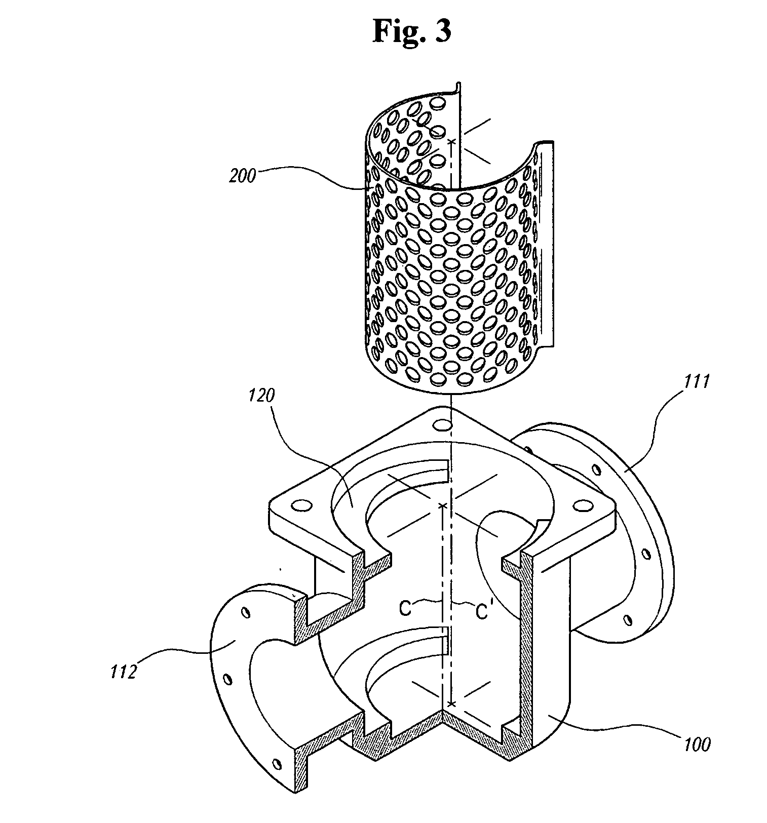
[0023]As shown in FIG. 3, the screen 200 according ...


PUM

PropertyMeasurementUnit
Durabilityaaaaaaaaaa

Abstract

A strainer is developed for mounting in a fluid system or a pipeline to filter the foreign objects remained in the fluid, thereby preventing malfunctioned operation, default and occlusion of the fluid machinery and the pipeline due to floating and drifting solids, and which includes an inlet and an outlet formed in a straight line and an omega-type screen joined to a cylindrical main body having a closed lower portion, thereby minimizing a transformation of a flow channel while maximally providing a screening face, and allowing a user to easily disassemble and clean the screen. The strainer can raise operational efficiencies of the fluid machine and the pipeline and remarkably reduce operational expenses by minimizing energy loss in the fluid, and reduce maintenance cost and ensure durability of the fluid machine and the pipeline by ensuring convenience in cleaning and maintaining the screen of the strainer.

Description

BACKGROUND OF THE INVENTION [0001]1. Field of the Invention[0002]The present invention relates to a strainer, which is mounted in a fluid machine or a pipeline to screen the fluid and collect solid foreign substances remaining in the fluid, thereby preventing erroneous operation, default and occlusion of the fluid machine and the pipeline due to floating and drifting solids, and more particularly, to a strainer, which includes an inlet and an outlet formed in a straight line and an omega-type screen joined to a cylindrical main body having a closed lower portion, thereby minimizing a transformation of a flow channel while maximally securing a screening face, and allowing a user to easily disassemble and clean the screen.[0003]2. Background Art[0004]A strainer is an essential accessory used in most of fluid machines and pipelines, and basically includes a screen for screening a fluid and a main body for supporting the screen and inducing the fluid to pass through the screen along a p...

Claims


Application Information

Patent Timeline
IPC IPC(8): B01D35/28
CPCB01D35/02B01D29/035F16L55/00F16L55/24
Inventor KIM, JEONG YEOL
Owner LEE EUI HO
Why Eureka
Try Eureka