System for manufacturing display unit

a display unit and manufacturing technology, applied in the direction of lamination ancillary operations, instruments, applications, etc., can solve the problems of manufacturing apparatus, stop the carrying of optical film f, etc., and achieve the effect of minimizing the transformation of optical film carried

Active Publication Date: 2020-10-13
SHANJIN OPTOELECTRONICS (NANJING) CO LTD
View PDF7 Cites 0 Cited by
  • Summary
  • Abstract
  • Description
  • Claims
  • Application Information

AI Technical Summary

Benefits of technology

[0009]The present invention has been made in an effort to provide a system for manufacturing a display unit, which minimizes a transformation of a carried optical film when a display unit is manufactured.
[0020]According to exemplary embodiments of the present invention, it is possible to minimize a transformation of an optical film carried to the system for manufacturing the display unit by the carrying unit.

Problems solved by technology

When the optical film is replaced, a display unit manufacturing apparatus has a failure, or a problem is generated in the carried optical film or the manufactured display unit during a process of manufacturing the display unit by attaching the optical film F to the panel P, the carrying of the optical film F may be stopped by a mistake of an operator, a change in a model of a display unit desired to be manufactured, and the like.

Method used


Image

  • System for manufacturing display unit
  • System for manufacturing display unit
  • System for manufacturing display unit

Examples


Embodiment Construction

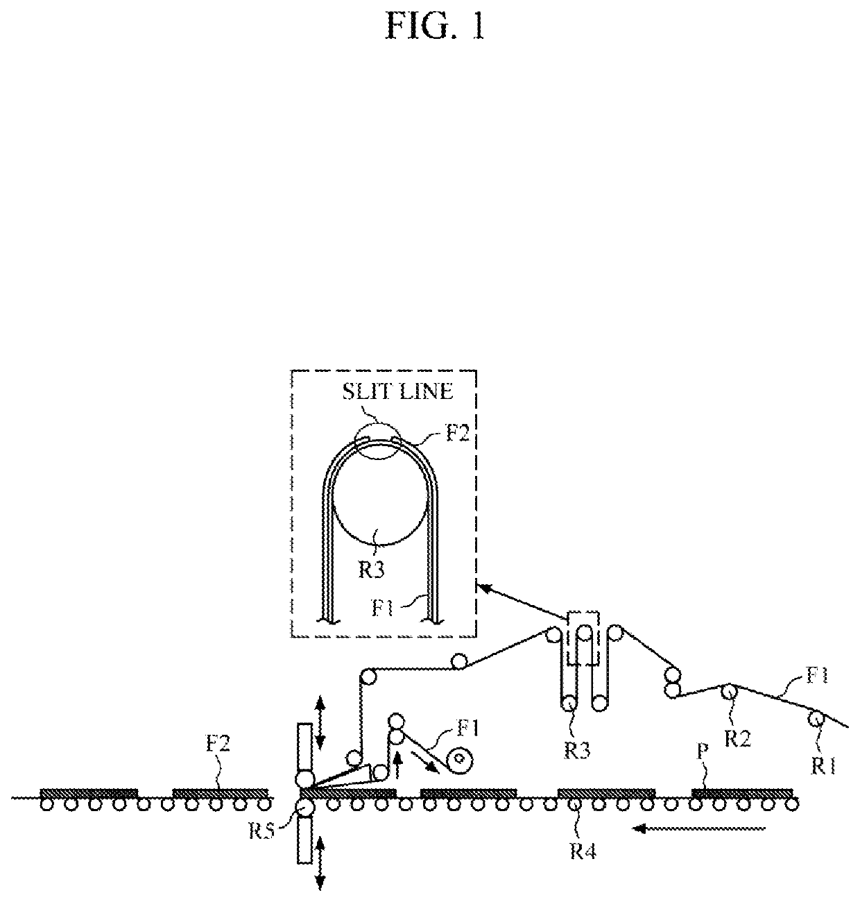
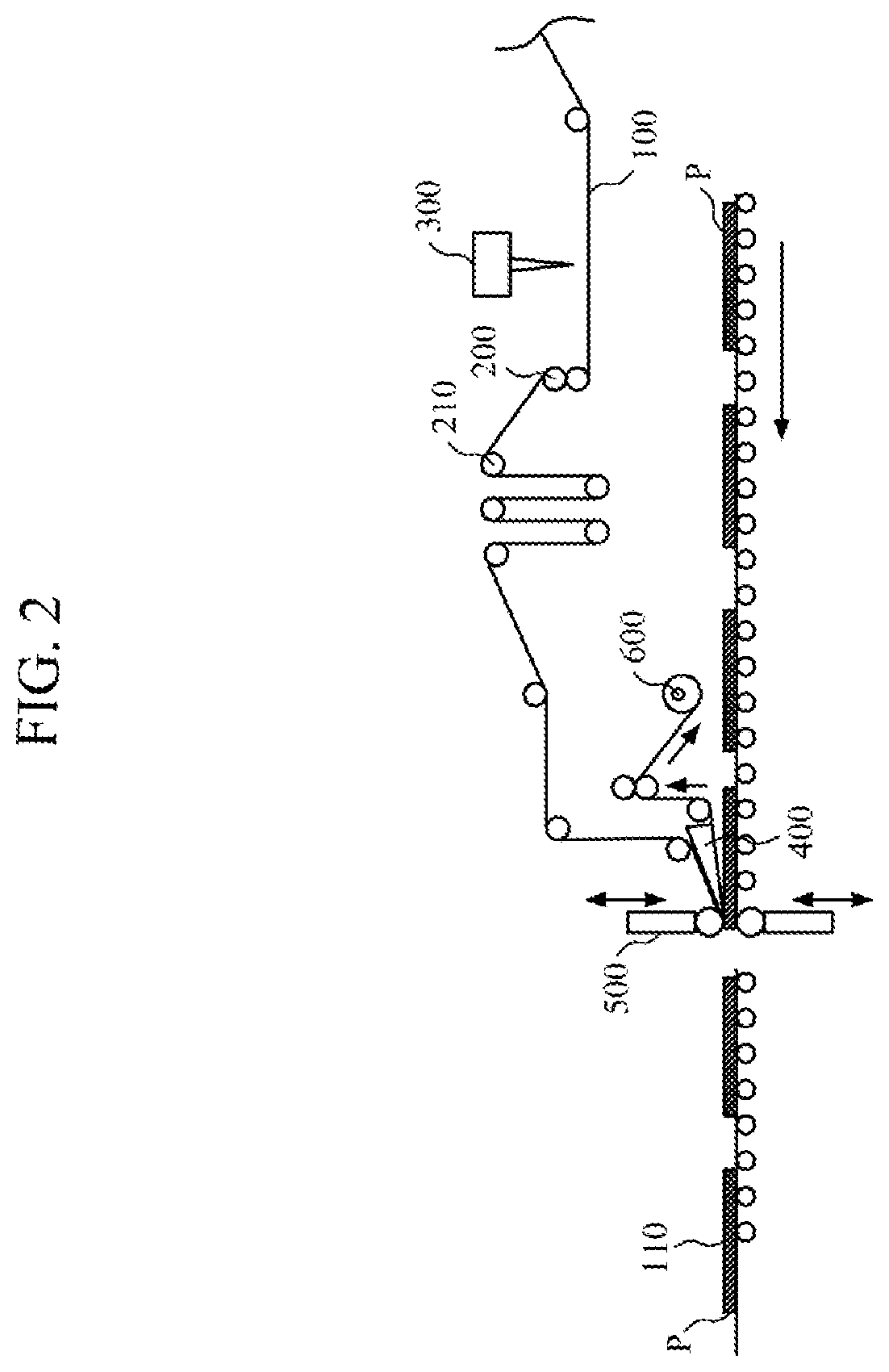
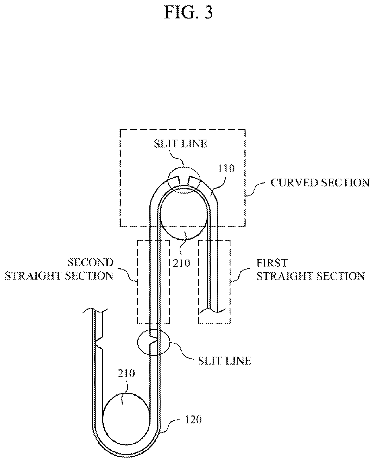
[0026]Hereinafter, the exemplary embodiments of the present invention will be described more fully with reference to the accompanying drawings so that those skilled in the art can easily carry out the present invention. However, the present invention may be modified in various different forms, are not limited to the exemplary embodiments described herein. A part irrelevant to the description will be omitted in the drawings to clearly describe the present invention, and the same elements will be designated by the same reference numerals throughout the specification.

[0027]Terms used in the present specification will be briefly described, and the present invention will be described in detail.

[0028]As the terms used in the present invention, general terms, which are currently and widely used in consideration of a function in the present invention, have been selected, but may be changed according to the intentions of those skilled in the art or judicial precedents, appearance of new tech...


PUM

PropertyMeasurementUnit
curvature radiusaaaaaaaaaa
thicknessaaaaaaaaaa
depthaaaaaaaaaa

Abstract

Disclosed is a system for manufacturing a display unit, including: a carrying unit configured to carry an optical film; a cutting unit configured to form a slit line on the optical film from a side opposite to the release film by a predetermined depth, in which the release film is not cut; a peeling unit configured to peel the polarizing film from the release film; and an attaching unit configured to attach the polarizing film peeled from the release film to a panel, in which the carrying unit includes a carrying direction changing unit, which changes a direction in which the optical film is carried so that the optical film carried along a first straight section is carried along a second straight section crossing the first straight section, and when the carrying of the optical film is stopped, the slit line formed on the optical film is positioned in the first straight section or the second straight section among the first straight section, the second straight section, and a curved section positioned between the first straight section and the second straight section.

Description

[0001]This application is a Utility Application which claims priority to and the benefit of Korean Patent Application No. 10-2016-0067659 filed on May 31, 2016, which is hereby incorporated by reference in its entirety herein.TECHNICAL FIELD[0002]The present invention relates to a system for manufacturing a display unit, and more particularly, to a system for manufacturing a display unit, which minimizes a transformation of a carried optical film when a display unit is manufactured.BACKGROUND ART[0003]A display unit including a liquid crystal display (LCD), an organic light emitting diode (OLED), a plasma display panel (PDP), and an electrophoretic display (EPD) is manufactured through several processes. In order to manufacture the display unit, an optical film is attached onto one surface and the other surface of a panel, and when an absorption axis of the optical film attached onto one surface of the panel is vertical to an absorption axis of the optical film attached onto the oth...

Claims


Application Information

Patent Timeline
Patent Type & Authority Patents(United States)
IPC IPC(8): B32B38/04G02F1/13G02F1/1335B32B41/00B32B38/00B32B38/10
CPCG02F1/1303B32B41/00B32B38/04B32B38/0004B32B38/10G02F2202/28B32B2309/70B32B2038/045G02F1/133528B32B2457/20
Inventor LEE, BEOM SEOKLEE, SUK JAEPARK, KYUNG HYEOKPARK, SANCHOI, HANG SUKJANG, EUNG JINJEUNG, BONG SURYOO, JEA HAN
Owner SHANJIN OPTOELECTRONICS (NANJING) CO LTD
Why Eureka
Try Eureka