
Tampon pledget having improved expansion and process for producing same

a technology of tampons and pledgets, which is applied in the field of absorbent catamenial tampon pledgets, can solve the problems of non-uniform absorption, discomfort of wearers, and insufficient absorption and expansion of conventional tampon pledgets to prevent fluid leakag

Inactive Publication Date: 2009-11-12
EVEREADY BATTERY CO INC
View PDF25 Cites 21 Cited by
  • Summary
  • Abstract
  • Description
  • Claims
  • Application Information

AI Technical Summary

Problems solved by technology

Conventional pledgets do not absorb and expand sufficiently rapidly to prevent fluid leakage.
Moreover, the typical high placement leads to non-uniform absorbency, which may contribute to bypass leakage.
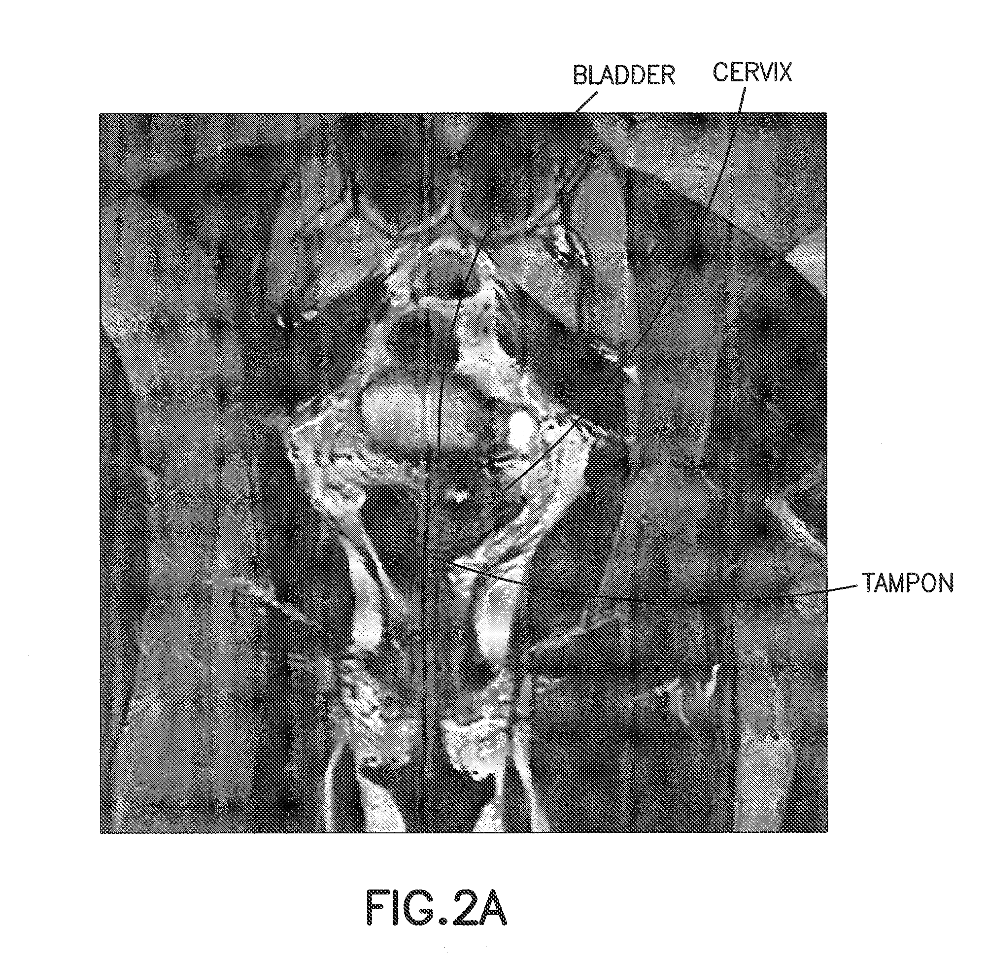
While it is preferable that women insert and position tampon pledget lower in the vaginal cavity (e.g., underneath the cervical os) to promote more uniform absorbency, it is believed that discomfort is experienced by the wearer when the tampon is located closer to the introitus.
Also, nerve endings are present in greater number near the introitus and thus may be irritated by the pressure exerted from the tampon.
Insertion of the tampon in this narrow, middle section can be uncomfortable.
As noted above, tampon pledget placement within the vaginal cavity can contribute to poor leakage performance.
While conventional tampon pledgets are highly absorbent, menstrual fluid can bypass a significant portion of the tampon pledget, causing bypass leakage with only a fraction of the potential tampon absorbency being utilized.
The inventors recognized that even though conventional tampons are highly absorbent, menstrual fluid typically bypasses a significant portion of the tampon resulting in leakage and only a fraction of the potential absorbency of the tampon being attained.

Method used


Image

  • Tampon pledget having improved expansion and process for producing same
  • Tampon pledget having improved expansion and process for producing same
  • Tampon pledget having improved expansion and process for producing same

Examples


Embodiment Construction

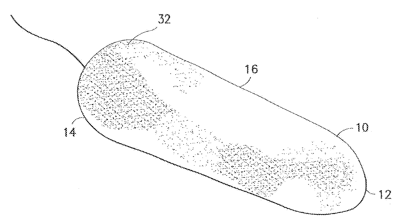
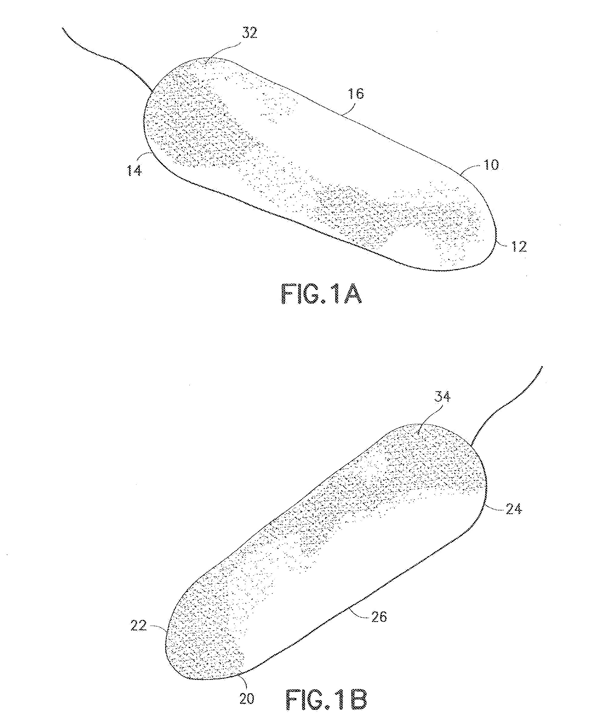
[0021]The inventors discovered that a pledget with increased absorption and / or expansion properties near the withdrawal end of the pledget is beneficial for leakage protection. The inventors also discovered that an essentially cylindrical tampon pledget provides comfort that consumers prefer.

[0022]FIG. 4 illustrates a tampon pledget 200 prior to use. The tampon pledget 200 is comprised of a mass of compressed fibrous material having an insertion end 202, a withdrawal end 204 and a string 206 coupled to the withdrawal end. As shown in FIG. 4, the tampon pledget 200 is cylindrical or columnar in shape over its total length L, shown generally at 220. The insertion end 202 has a diameter A. The withdrawal end 204 has a diameter B. In one embodiment, prior to use and expansion, the diameter B is at least equal to or about ten percent (10%) greater that the diameter A. In one embodiment, diameter A is about 13.9 mm and diameter B is about 15.3 mm.

[0023]FIG. 5 illustrates one embodiment of...


PUM


Abstract

A feminine hygiene product is presented. The feminine hygiene product includes a body having a mass of compressed fibrous material, an insertion end and a withdrawal end. The body has an overall length L. The insertion end has a diameter A and the withdrawal end has a diameter B. In an initial state, diameter B is at least about equal to up to about ten percent greater than the diameter A. When exposed to a fluid, diameter B radially expands such that a ratio of diameter B to the diameter A is about 1.25 to 1. In one embodiment, the feminine hygiene product is a vaginal tampon and when exposed to a fluid, diameter B expands more rapidly than diameter A to substantially seal a bottom portion of a vaginal cavity and prevent bypass leakage.

Description

BACKGROUND OF THE INVENTION[0001]1. Field of the Invention[0002]This invention relates generally to absorbent catamenial tampon pledgets and methods for making such tampon pledgets. More particularly, the present invention relates to tampon pledgets having improved expansion and absorbency characteristics at a withdrawal end to improve leakage protection.[0003]2. Description of the Related Art[0004]The human female vagina is located in the lower pelvic cavity and is surrounded by organs such as the uterus, the bladder, and the rectum. The vagina is a collapsed tube-like structure composed of fibromuscular tissue layers that extends from the uterus inside the body to the vulva on the exterior of the body. The entrance to the vagina, the introitus, is of a relatively small diameter, a lower two-thirds of the vagina is only slightly larger in diameter (if at all) than the introitus, and an upper third (nearest the cervix of the uterus) is the widest diameter. From a biological perspect...

Claims


Application Information

Patent Timeline
IPC IPC(8): A61F13/20
CPCA61F13/2051A61F13/2085A61F13/2065A61F13/208A61F13/20
Inventor DOUGHERTY, JR., EUGENEEDGETT, KEITHJORGENSEN, ROBERT
Owner EVEREADY BATTERY CO INC
Learn More