
Imaging apparatus

a technology of imaging apparatus and touch panel, which is applied in the direction of portable computer details, instruments, printing, etc., can solve the problems of deteriorating the width of the imaging apparatus is too small for a user to firmly hold the imaging apparatus with both hands, and the user cannot firmly hold the imaging apparatus, so as to achieve the effect of maintaining the visibility of the display screen and the operability of the touch panel

Active Publication Date: 2009-11-12
NINTENDO CO LTD
View PDF72 Cites 64 Cited by
  • Summary
  • Abstract
  • Description
  • Claims
  • Application Information

AI Technical Summary

Benefits of technology

[0009]Therefore, an object of the present invention is to provide an imaging apparatus which is capable of being held by a user while maintaining visibility of a display screen and operability of a touch panel when taking an image.

Problems solved by technology

Thus, a width of the imaging apparatus is too small for a user to firmly hold the imaging apparatus with both hands.
Further, since the display screen is provided across the entirety of the surface of each housing, when the user holds the imaging apparatus either lengthwise or sideways, fingers are located on the screen, thereby deteriorating visibility of the screen and operability of the touch panel.
On the other hand, when the user holds the imaging apparatus such that the fingers are not located on the screens, the user has to hold the imaging apparatus at back surfaces and side surfaces of the housings, and hence cannot firmly hold the imaging apparatus.
Further, since the information apparatus disclosed in the Patent Document 2 is a notebook computer, it is assumed that the notebook computer is used in a placed state when taking an image, and the notebook computer cannot be held with hands and used when taking an image.
Thus, there is a problem that there is a high probability that hand movement occurs when taking an image.
Further, since the imaging apparatus cannot be firmly held when taking an image, it is hard to perform an operation when taking an image.

Method used


Image

  • Imaging apparatus
  • Imaging apparatus
  • Imaging apparatus

Examples


Embodiment Construction

[0061](Configuration of Imaging Apparatus)

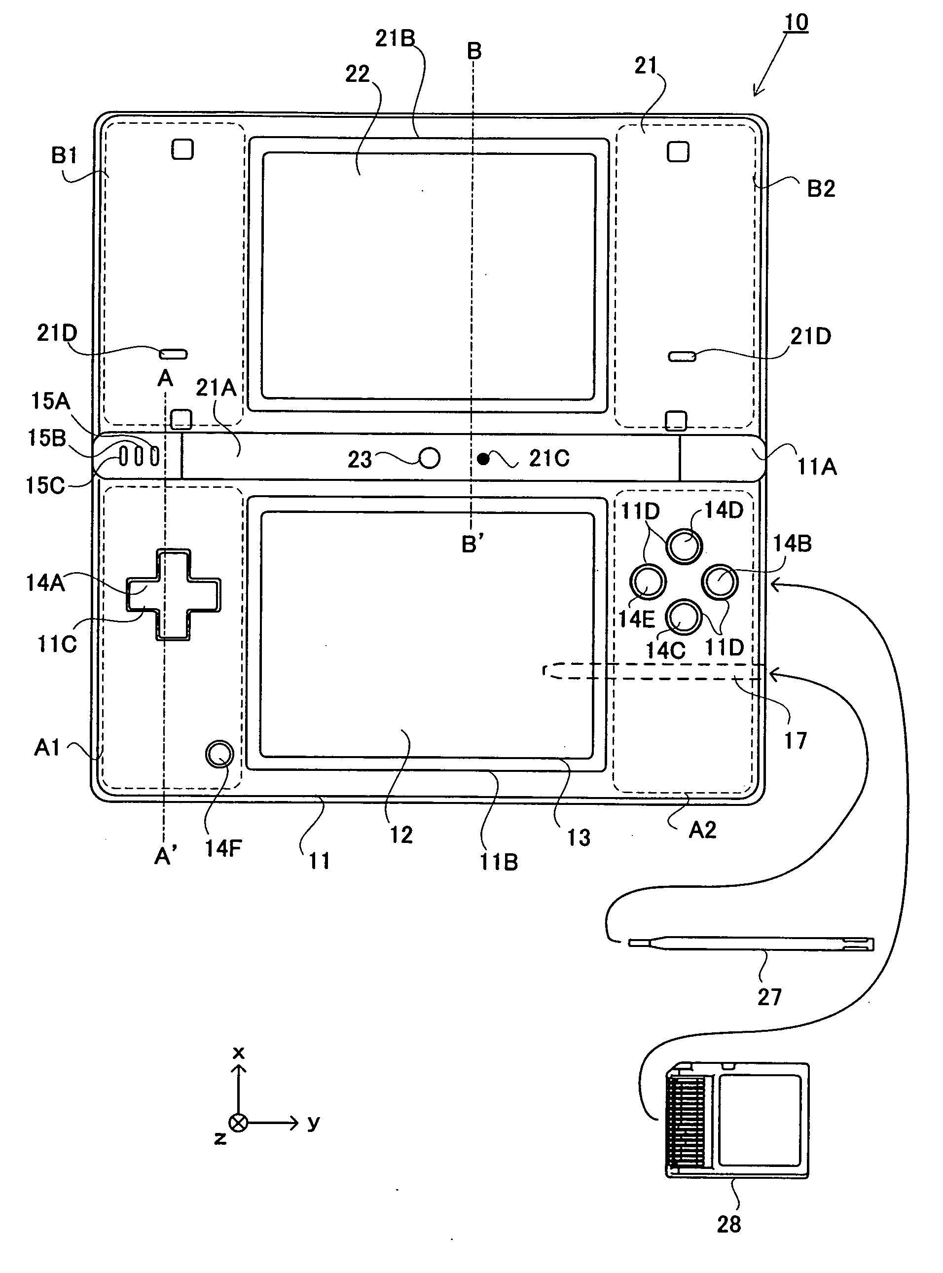
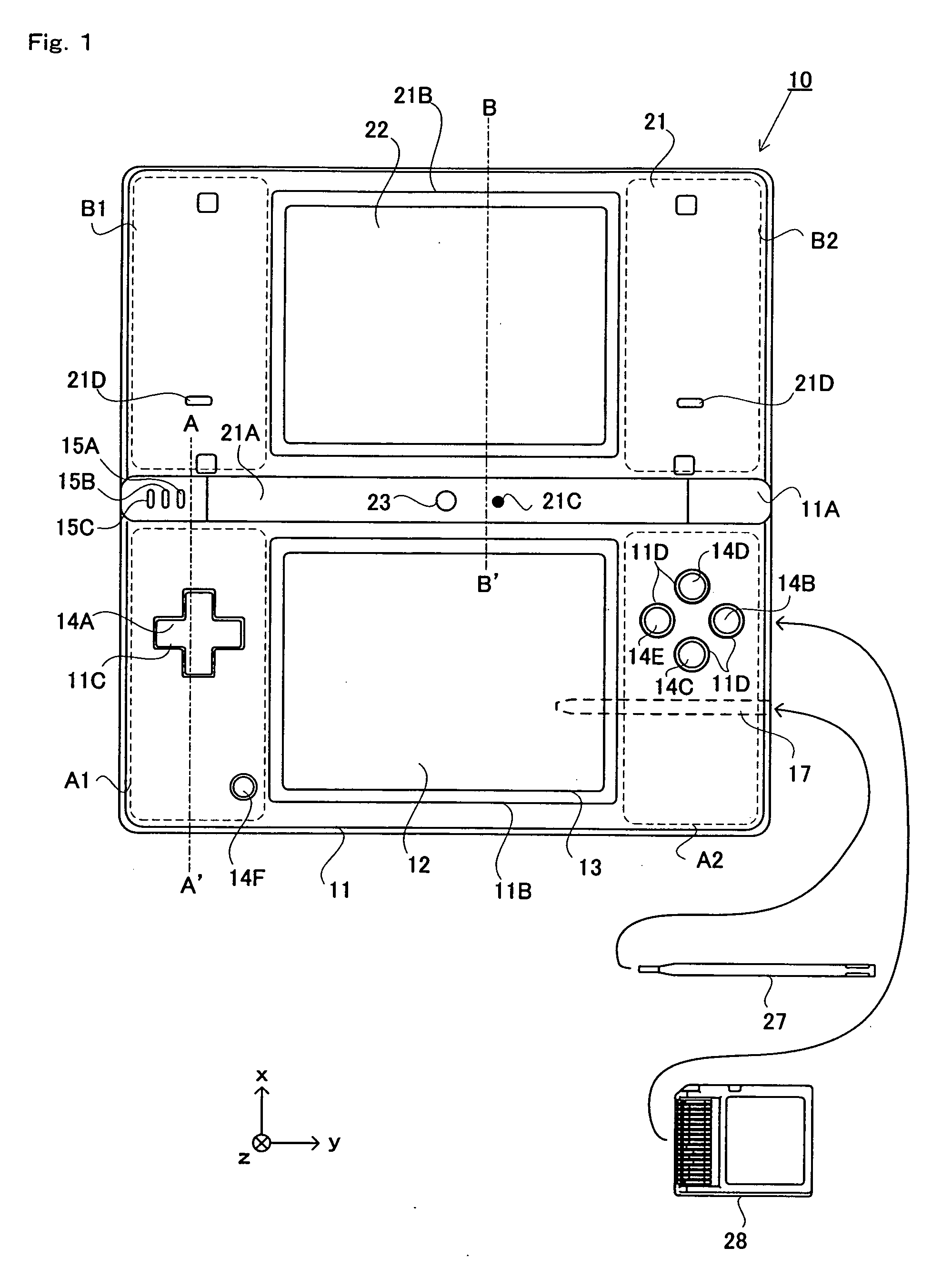
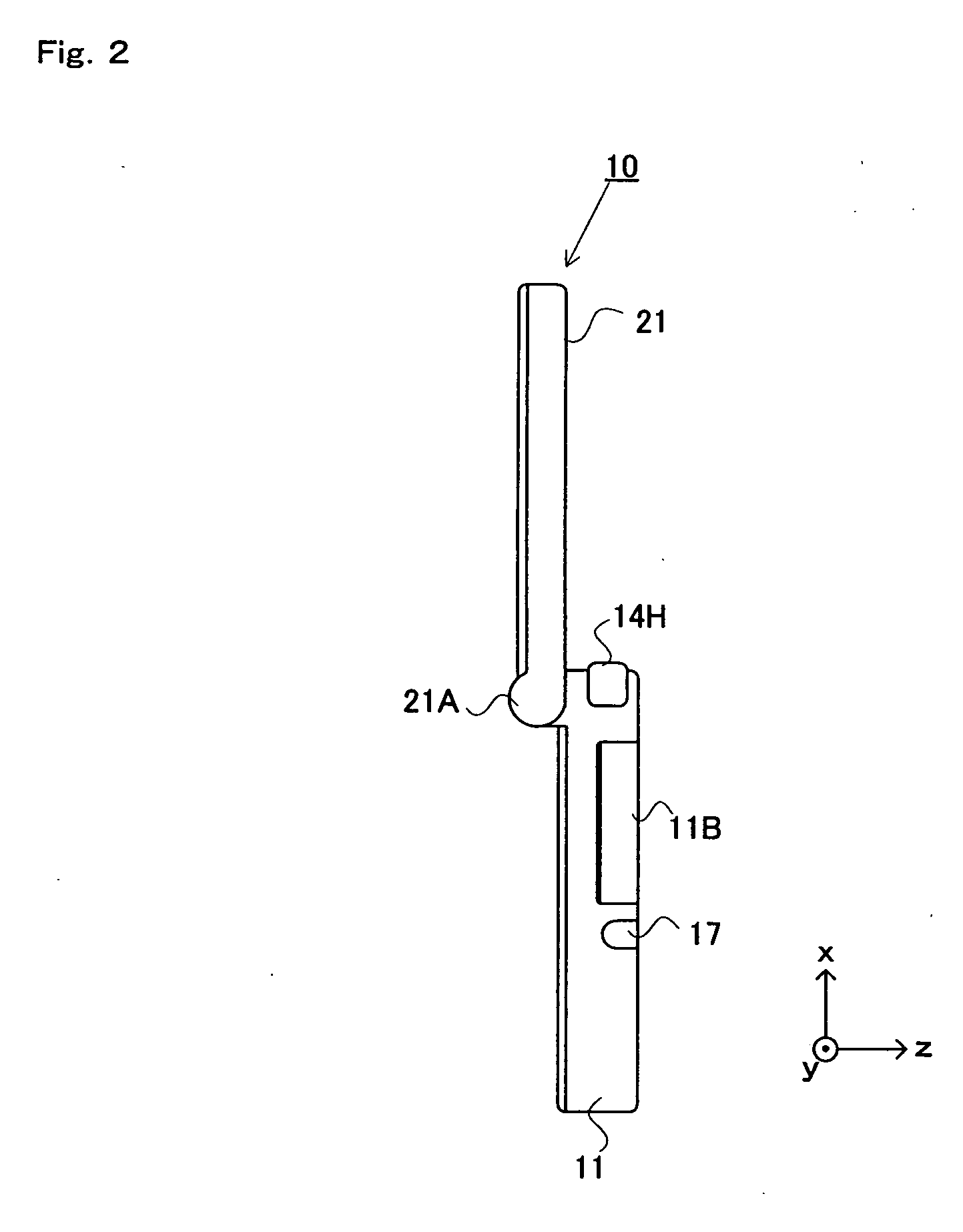
[0062]The following will describe an imaging apparatus according to an embodiment of the present invention. FIGS. 1 to 3 are external plan views of the imaging apparatus 10. The imaging apparatus 10 is a foldable imaging apparatus, FIGS. 1 and 2 show the imaging apparatus 10 in an opened state, and FIGS. 3A to 3D show the imaging apparatus 10 in a closed state. More specifically, FIG. 1 is a front view of the imaging apparatus 10 in the opened state, and FIG. 2 is a side view of the imaging apparatus in the opened state. The imaging apparatus 10 takes an image with a camera, displays the taken image on a screen, and stores data of the taken image. The imaging apparatus 10 includes two display devices (LCDs 12 and 22) and two cameras (cameras 23 and 25).

[0063]FIGS. 15 to 17 are external plan views of an imaging apparatus according to a modified example of the present embodiment. FIG. 15 is a front view of the imaging apparatus 10 in an opened...


PUM


Abstract

An imaging apparatus 10 includes a lower housing 11, an upper housing 21, a lower LCD 12, an outer camera, a plurality of buttons 14A to 14E, and a touch panel 13. The lower housing 11 has a horizontally long shape. The upper housing 21 has a horizontally long shape, and a long side of the upper housing 21 is connected to an upper long side of the lower housing 11 such that the lower housing 11 and the upper housing 21 are foldable. The lower LCD 12 has a display screen which is provided in an inner surface of the lower housing 11. The outer camera is provided in an outer surface of the upper housing 21, and located at an end of the outer surface of the upper housing 21 which is opposite to a connection portion where the upper housing 21 is connected to the lower housing 11. The plurality of buttons 14A to 14E are provided on an inner surface of the lower housing 11 and on both sides of the display screen in a horizontal direction of the lower housing 11. The touch panel 13 is provided on the display screen.

Description

CROSS REFERENCE TO RELATED APPLICATION[0001]The disclosure of Japanese Patent Application No. 2008-109032, filed on Apr. 28, 2008, is incorporated herein by reference.BACKGROUND OF THE INVENTION[0002]1. Field of the Invention[0003]The present invention relates to an imaging apparatus, and more particularly to an imaging apparatus which is held and used by a user when taking an image.[0004]2. Description of the Background Art[0005]Conventionally, there exists an imaging apparatus which takes an image with a camera and displays the taken image on a display device. For example, Patent Document 1 (Japanese Laid-Open Patent Publication No. 2006-311224) discloses an imaging apparatus which is a foldable mobile phone having an imaging function. The imaging apparatus includes two vertically long housings which are connected to each other at short sides thereof so as to be foldable, and a display screen is provided in each housing. Further, a touch panel is provided on each display screen. I...

Claims


Application Information

Patent Timeline
Patent Type & Authority Applications(United States)
IPC IPC(8): G09G5/00H04N13/239
CPCA63F2300/1075A63F2300/204G03B29/00G06F1/1616G06F1/1647G06F1/1656H04N13/0239G06F1/1692G06F2200/1614H04N5/2251H04N5/23293H04N5/2621G06F1/1686H04N13/239H04N23/531H04N23/632H04N23/635
Inventor KUWAHARAKOSHIISHI, KAZUNORIEHARA, YUI
Owner NINTENDO CO LTD
Learn More