
System for Stabilizing at Least a Portion of the Spine

a technology of a system of stabilization, which is applied in the field of system and method for stabilizing at least a portion of the spine, can solve the problems of unfavorable situation, no degree of freedom between the sacrum and the last lumbar vertebra,

Inactive Publication Date: 2009-10-29
ZIMMER SPINE SAS
View PDF39 Cites 97 Cited by
  • Summary
  • Abstract
  • Description
  • Claims
  • Application Information

AI Technical Summary

Benefits of technology

[0005]To solve this problem, at least one object of the present disclosure is to provide a system for stabilizing the sacrum and at least the fifth lumbar vertebra that makes dynamic stabilization possible. For this particular embodiment of the disclosure, the term “dynamic stabilization” is used to mean that the sacrum and at least the last lumbar vertebra are indeed stabilized relative to each other, but that a limited amount of relative movement is nevertheless allowed between the vertebra and the sacrum so as to enable the patient to be more comfortable.
[0016]It will be understood that because of the presence of the second spacer, the tie enables both the fifth and the fourth lumbar vertebrae to be stabilized with the sacrum, while also allowing relative movement between the sacrum, the fifth lumbar vertebra, and the fourth lumbar vertebra. Naturally, it is possible to provide more than one second spacer should it be appropriate to stabilize more than two vertebrae with the sacrum.

Problems solved by technology

Those devices are very effective, but they prevent the vertebra(e) from moving relative to the sacrum in a manner that is practically total, thus leaving no degree of freedom between the sacrum and the last lumbar vertebra.
In many circumstances, that situation is unfavorable.

Method used


Image

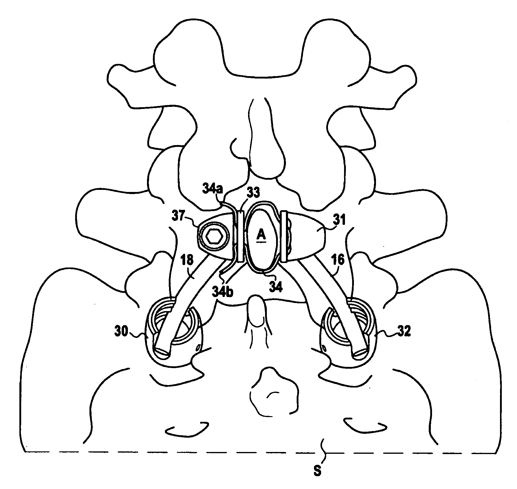
  • System for Stabilizing at Least a Portion of the Spine
  • System for Stabilizing at Least a Portion of the Spine
  • System for Stabilizing at Least a Portion of the Spine

Examples


first embodiment

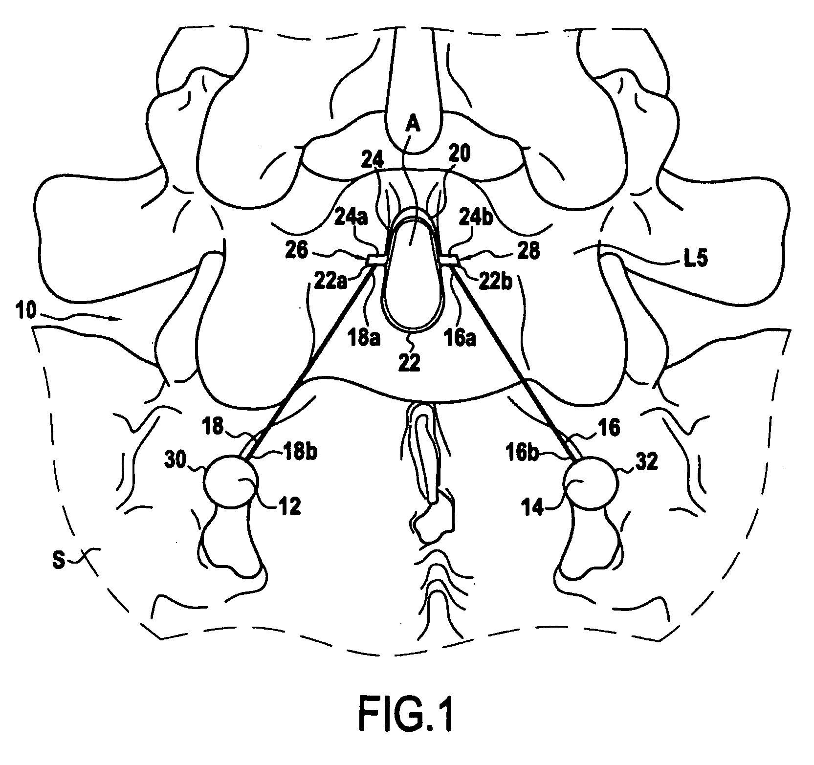
[0028]With reference initially to FIG. 1, there follows a description of the dynamic stabilizer system.

[0029]In this figure, there can be seen the upper portion of the sacrum S together with the lower lumbar vertebra L5 and its spinous process A.

[0030]The dynamic stabilizer system, given overall reference 10, is constituted by two anchoring members 12 and 14 preferably constituted by screws screwed into the sacrum, by two rigid rods 16 and 18, and by a mechanical fastener element fastened to the process A, and given reference 20. As explained above, the mechanical element fastened to the process includes a flexible portion that is constituted, in this embodiment, by two flexible tie portions 22 and 24. The ends 22a, 22b and 24a, 24b of these ties are secured to one another in such a manner that the assembly constituted by the tie portions 22 and 24 completely surrounds the spinous process A. The ends 22a, 24a and 22b, 24b of the tie portions constitute fastener ends of the mechanica...

second embodiment

[0038]FIGS. 2 to 4 show the disclosure that is described below.

[0039]In this second embodiment, the dynamic stabilizer system is given reference 10′ and it is constituted by two screws 40 and 42 that constitute the anchoring members in the sacrum S, by two rigid rods 44 and 46, and by a mechanical fastener element referenced 20′ for fastening to the spinous process A of the vertebra L5. In this embodiment, the mechanical fastener element 20′ is essentially constituted by an intervertebral spacer 48 and by a flexible tie 50.

[0040]The spacer 48 is interposed between the spinous process A of the vertebra L5 and the spinous process S1 of the sacrum S. More precisely, the spacer 48 has two end portions 52 and 54, each provided with a recess 56, 58 for receiving the spinous processes A and S1. As explained in greater detail below, the spacer 48 serves both for fastening to one of the ends of each of the rigid rods 44 and 46, and for securing the ends of the flexible braid 50.

[0041]Prefera...


PUM


Abstract

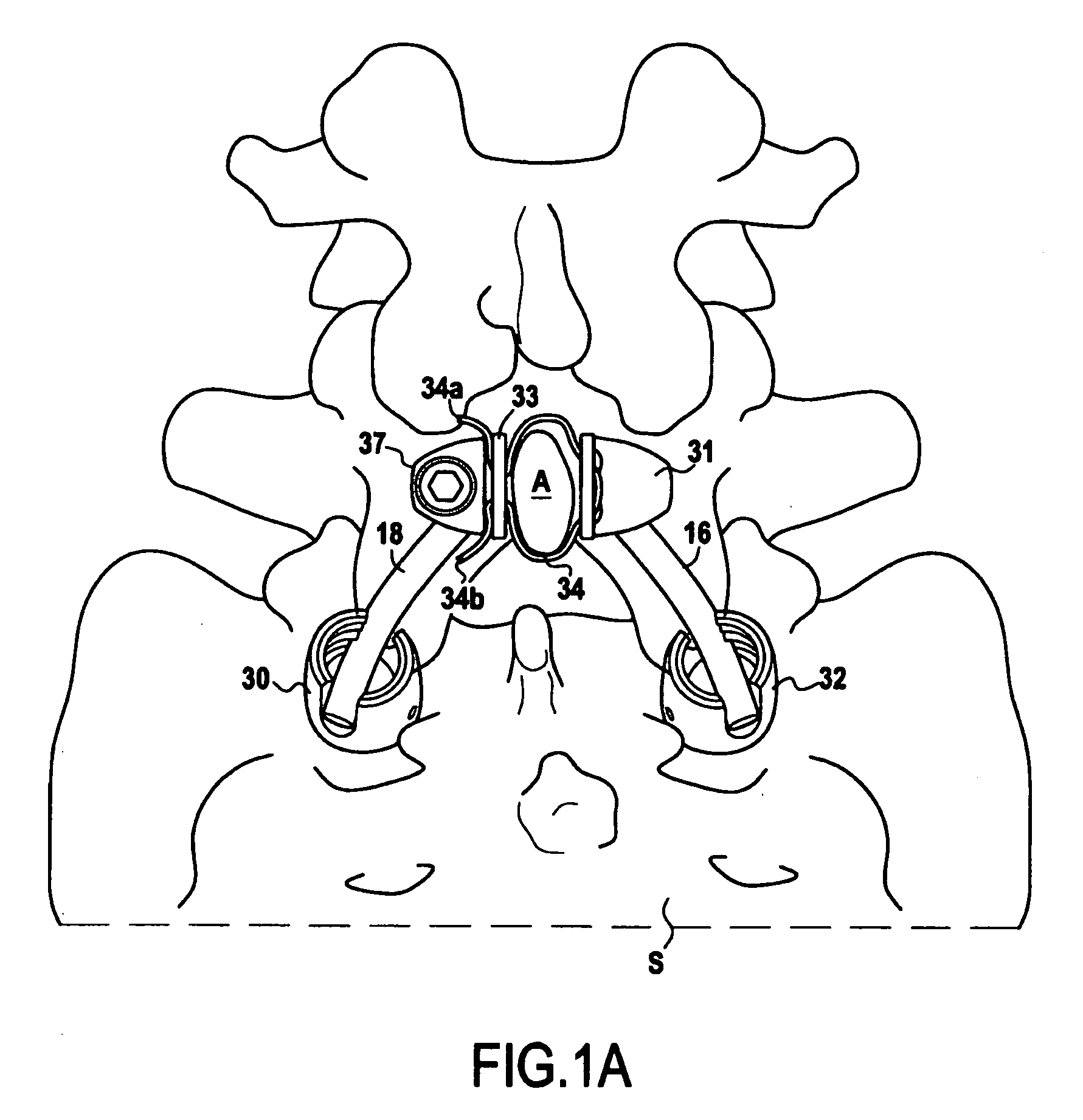
Disclosed are embodiments of a dynamic stabilizer system for dynamically stabilizing the sacrum and at least lumbar vertebra L5. The dynamic stabilizer system may comprise two anchoring members that can be implanted at distinct locations in the sacrum, a mechanical fastener element having two ends and a flexible portion that can be securely fastened on the spinous process of a lumbar vertebra, and two distinct rods, each securing onto the anchoring members and the mechanical fastener element. In some embodiments, the dynamic stabilizer system may further comprise one or more spacers, each interposed between two spinous processes. The mechanical fastener element further comprises features for securing the one or more spacers.

Description

CROSS-REFERENCE TO RELATED APPLICATION[0001]This application claims a benefit of priority under 35 U.S.C. 119(a) of the filing date of European Patent Application No. 08305124, entitled “System for Stabilizing at Least a Portion of the Spine” by inventors Stephane Douget and Vincent Pointillart, filed on Apr. 24, 2008, the content of which application is hereby incorporated as if fully set forth herein.TECHNICAL FIELD OF THE DISCLOSURE[0002]The present disclosure includes a system and method for stabilizing at least a portion of the spine, including in at least one embodiment a system for dynamically stabilizing the sacrum and at least lumbar vertebra L5.SUMMARY OF THE DISCLOSURE[0003]PCT patent applications Nos. WO 2005 / 020860, WO 2006 / 106268, and WO 2007 / 023240, which are incorporated herein by reference, describe systems for stabilizing the sacrum to the fifth lumbar vertebra.[0004]Those devices are very effective, but they prevent the vertebra(e) from moving relative to the sacr...

Claims


Application Information

Patent Timeline
IPC IPC(8): A61B17/70
CPCA61B17/7011A61B17/7055A61B17/842A61B17/7067A61B17/7062
Inventor DOUGET, STEPHANEPOINTILLART, VINCENT
Owner ZIMMER SPINE SAS
Learn More