
Substrate processing apparatus and substrate transfer method adopted therein

a substrate processing and substrate technology, applied in the direction of thin material processing, instruments, article separation, etc., can solve the problems of affecting the subsequent processes to a significant extent, affecting the quality of the semiconductor devices formed from the product wafer as final products, undesirable situation, etc., to prevent the destabilization of the conditions inside the processing chamber attributable to the interrupt substrate processing. , to prevent the effect of reliably preventing the destabilization of the conditions inside the processing chamber

Active Publication Date: 2009-10-29
TOKYO ELECTRON LTD
View PDF21 Cites 14 Cited by
  • Summary
  • Abstract
  • Description
  • Claims
  • Application Information

AI Technical Summary

Benefits of technology

[0013]According to the present invention described above, an interrupt substrate is not immediately transferred if the interrupt start button is depressed while the normal transfer pattern cycle is in progress as control for taking out individual substrates from the substrate storage containers in the order defined in the normal transfer pattern is repeatedly executed. Instead, the interrupt substrate is transferred in the order defined in the interrupt transfer pattern after the cycle is completed. In addition, the interrupt transfer pattern is defined by modifying the normal transfer pattern with some product substrates in the normal transfer pattern replaced with interrupt substrates, and once the interrupt transfer pattern cycle ends, the operation reverts to the normal transfer pattern cycle. By regulating the timing with which interrupt substrates are transferred based upon the normal transfer pattern or the interrupt transfer pattern as described above, the cleaning process can be executed with uniform timing regardless of the timing with which the interrupt start button is depressed. Consequently, destabilization of the conditions inside the processing chamber attributable to the interrupt substrate processing can be prevented reliably.
[0015]At the substrate processing apparatus that executes the cleaning process by transferring into the processing chamber a single dummy substrate after processing a single product substrate or a plurality of product substrates, a decision as to whether or not the normal transfer pattern cycle or the interrupt transfer pattern cycle has ended may be made by determining based upon the transfer history whether or not the substrate transferred immediately before depression of the interrupt start button is a dummy substrate. Based upon these transfer patterns, it is ensured that a dummy substrate is invariably transferred at the end of each cycle. This means that if the substrate transferred immediately before a depression of the interrupt start button is not a dummy substrate, the particular transfer pattern cycle has not ended and that if the substrate transferred immediately before a depression of the interrupt start button is a dummy substrate, the particular transfer pattern has ended. In this manner, the decision as to whether or not the transfer pattern cycle has ended can be made with ease.
[0016]In addition, the interrupt transfer pattern may be determined based upon, for instance, a specific number of interrupt substrates. If the specific number of interrupt substrates is equal to or smaller than the specific number of product substrates mentioned earlier, the transfer pattern achieved by replacing all or some of the product substrates in the normal transfer pattern with interrupt substrates may be designated as the interrupt transfer pattern. If, on the other hand, the specific number of interrupt substrates exceeds the specific number of product substrates, a plurality of transfer patterns achieved by replacing all or some of the product substrates in the normal transfer pattern with interrupt substrates may be designated as the interrupt transfer pattern. By defining the interrupt transfer pattern in correspondence to the number of interrupt substrates as described above, a desired number of interrupt substrates can be transferred for interrupt processing in without disrupting the timing of the cleaning process.
[0019]According to the present invention described above, regardless of the timing with which the interrupt start button is depressed while the manufacturing process and the cleaning process are repeatedly executed through similar cycles in the individual processing chambers, the interrupt substrate processing can be executed in the desired processing chamber among the plurality of processing chambers without disrupting the timing with which the cleaning process is executed in the particular processing chamber. Consequently, destabilization of the conditions inside the processing chamber attributable to the interrupt substrate processing can be prevented reliably.
[0020]According to the present convention, which enables execution of the interrupt substrate processing without disrupting the timing of the cleaning process by regulating the timing with which the interrupt substrates are transferred, a substrate processing apparatus and a substrate transfer method adopted therein, that reliably prevent destabilization of the conditions inside the processing chamber, are provided.

Problems solved by technology

For instance, particles remaining on the substrate stage disposed inside the processing chamber may adhere to the rear surface of the product wafer placed on the stage and this may adversely affect the subsequent processes to a significant extent.
In addition, particles remaining inside the processing chamber may settle onto the product wafer and affect the processing of the product wafer, which would compromise the quality of the semiconductor devices formed from the product wafer as final products.
However, since the timing with which the interrupt wafer is transferred is not specially regulated in the related art, the interrupt wafer is taken out of the substrate storage container immediately in response to the interrupt start operation.
This gives rise to an undesirable situation that may occur in the substrate processing apparatus that executes the cleaning process with specific timing following the processing executed on the specific number of product wafers, as described earlier, in that depending upon the timing of the interrupt start operation, the interrupt wafer may be transferred in succession with respect to a product wafer.
As a result, the timing with which the cleaning process is executed inside the processing chamber will be disrupted which, in turn, will destabilize the conditions inside the processing chamber and ultimately cause inconsistency in the results of the manufacturing process executed on the individual wafers.

Method used


Image

  • Substrate processing apparatus and substrate transfer method adopted therein
  • Substrate processing apparatus and substrate transfer method adopted therein
  • Substrate processing apparatus and substrate transfer method adopted therein

Examples


Embodiment Construction

[0038]The following is a detailed explanation of preferred embodiments of the present invention, given in reference to the attached drawings. It is to be noted that in the specification and the drawings, the same reference numerals are assigned to components having substantially identical functions and structural features to preclude the necessity for a repeated explanation thereof.

[0039](Structural Example of Substrate Processing Apparatus)

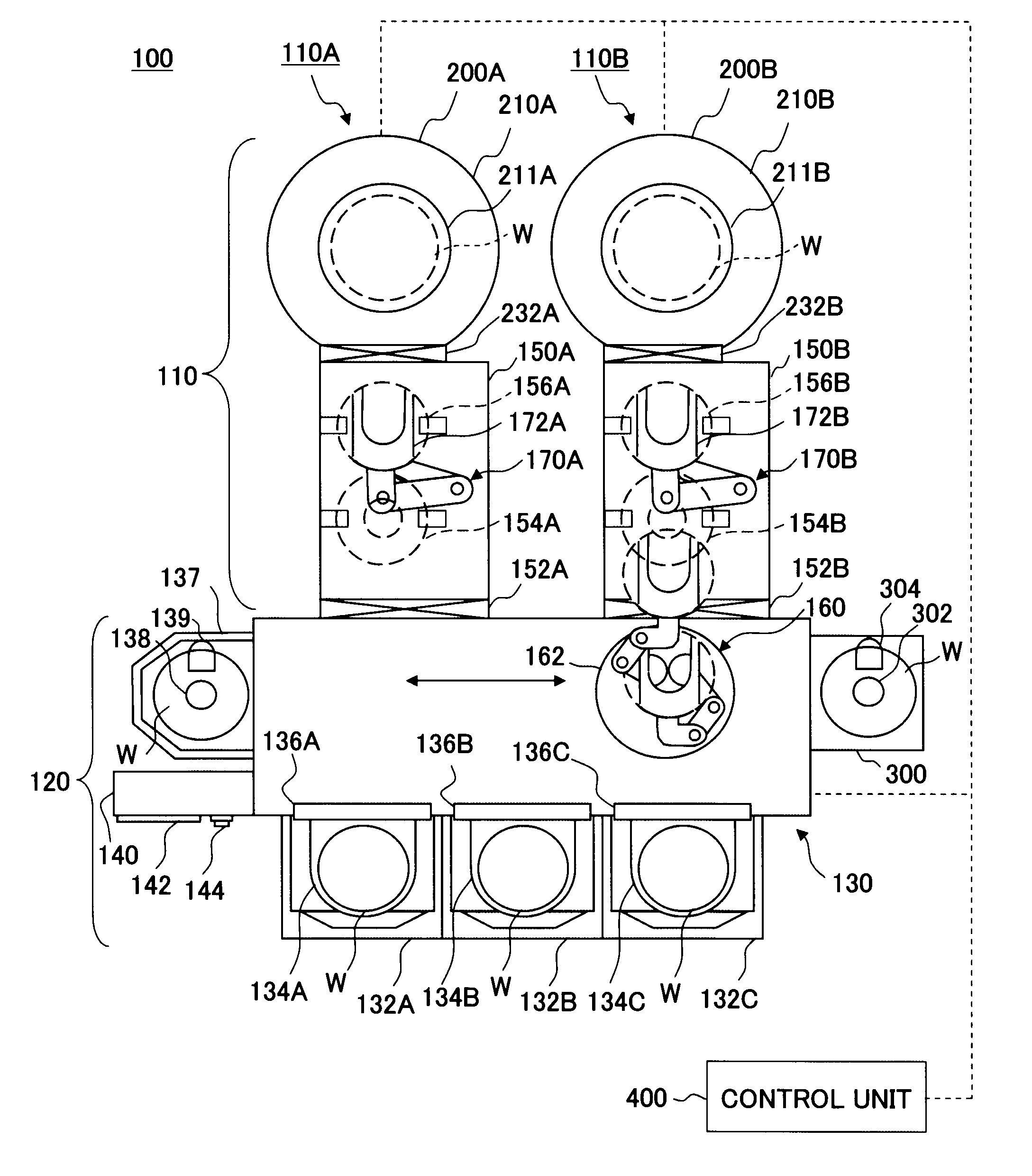
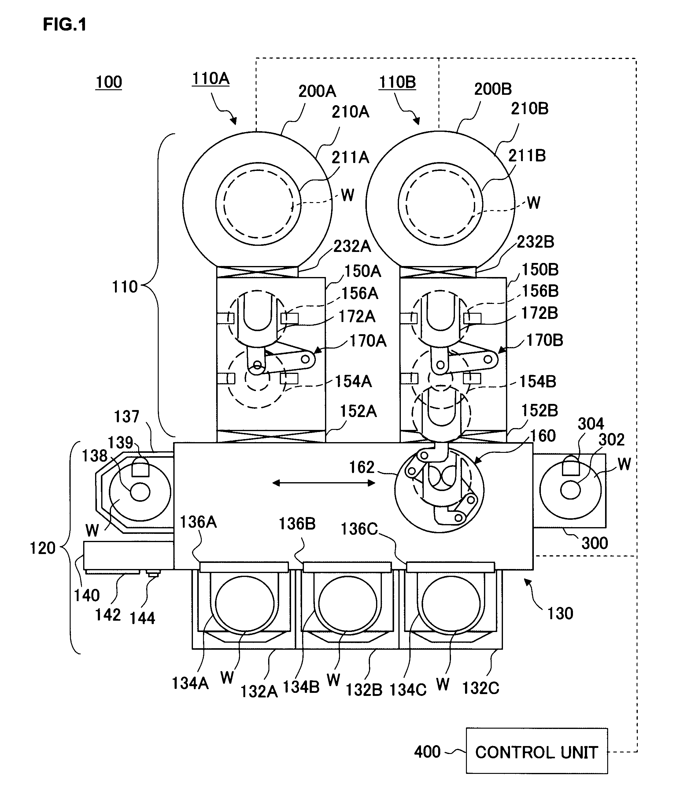
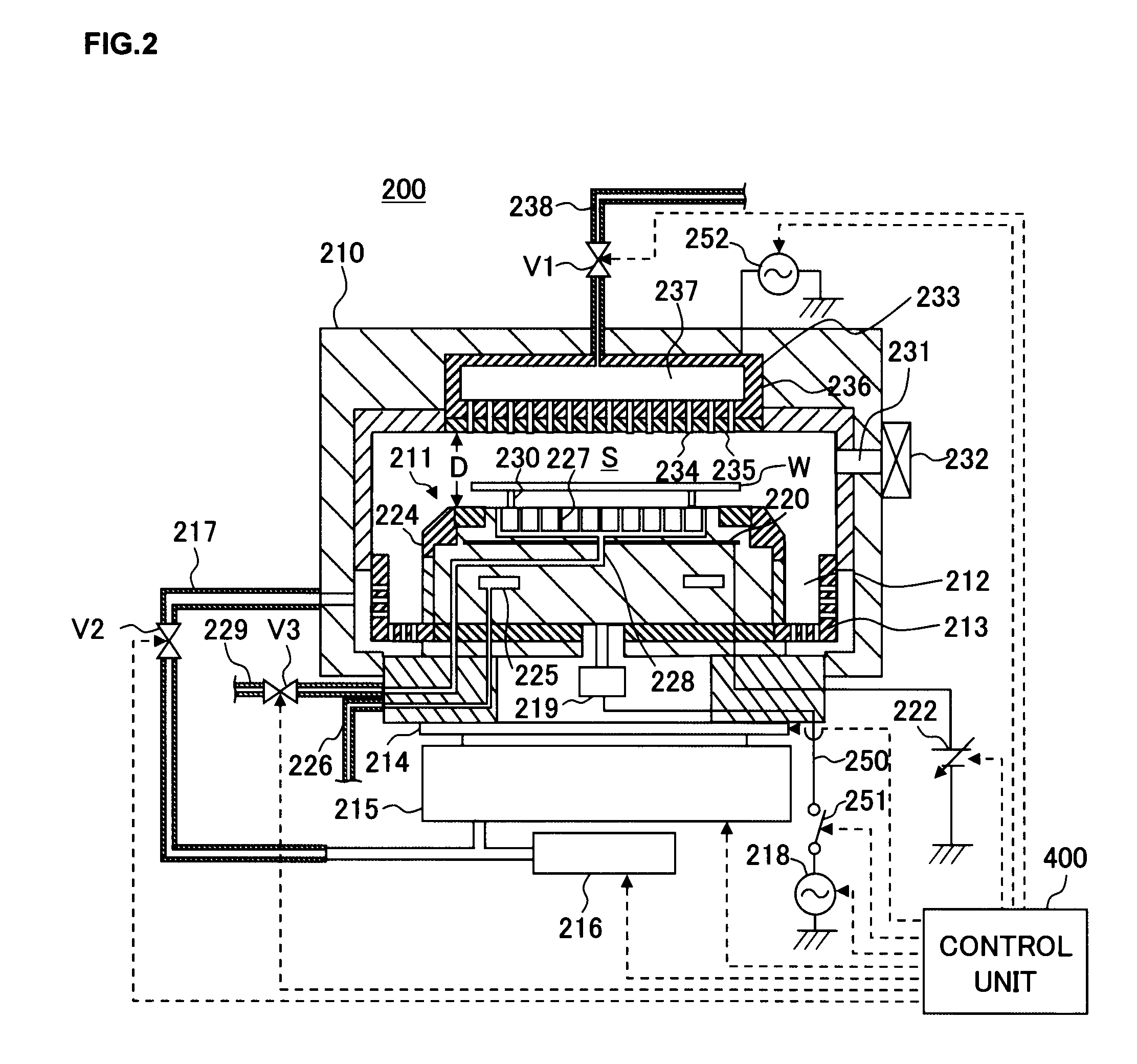
[0040]First, the substrate processing apparatus achieved in an embodiment of the present invention is explained in reference to drawings. The following description is given on an example in which the present invention is adopted in a substrate processing apparatus with at least one vacuum processing unit connected to a transfer chamber. FIG. 1 is a sectional view schematically showing the structure adopted in the substrate processing apparatus in an embodiment of the present invention.

[0041]The substrate processing apparatus 100 includes a single...


PUM


Abstract

As an interrupt start button is depressed while control, under which product wafers Wp and dummy wafers Wd are transferred in an order defined in a normal transfer pattern, is repeatedly executed, a decision is made based upon wafer transfer history as to whether or not the most recent transfer pattern cycle has ended. If the cycle is determined to have ended, the operation immediately proceeds to the subsequent cycle to transfer interrupt wafers Wf and Wd in an order defined in the interrupt transfer pattern achieved by replacing Wp in the normal transfer pattern with Wf, whereas if the cycle is determined to be incomplete, the wafer transfer based upon the normal transfer pattern is carried on until the cycle ends and then the operation proceeds to the next cycle to transfer Wf and Wd in the order defined in the interrupt transfer pattern.

Description

CROSS-REFERENCE TO RELATED APPLICATIONS[0001]This document claims priority to Japanese Patent Application Number 2008-117043, filed on Apr. 28, 2008 and U.S. Provisional Application No. 61 / 082,066, filed on Jul. 18, 2008, the entire content of which are hereby incorporated by reference.FIELD OF THE INVENTION[0002]The present invention relates to a substrate processing apparatus that transfers substrates such as semiconductor wafers or FPD (flat-panel display) substrates one at a time from a substrate storage container into a processing chamber and executes a specific type of processing on the substrate having been carried into the processing chamber. It also relates to a substrate transfer method adopted in the substrate processing apparatus.BACKGROUND OF THE INVENTION[0003]In a substrate processing apparatus such as a plasma processing apparatus used to manufacture semiconductor devices, product wafers in a substrate storage container are taken out of the substrate storage containe...

Claims


Application Information

Patent Timeline
Patent Type & Authority Applications(United States)
IPC IPC(8): H01L21/67
CPCH01L21/67253H01L21/67754H01L21/67748G05B19/41815G05B19/4189H01L21/67742G05B2219/45031
Inventor IIJIMA, KIYOHITOMOCHIZUKI, HIROAKINUMAKURA, MASAHIRO
Owner TOKYO ELECTRON LTD
Learn More