Agile high resolution arbitrary waveform generator with jitterless frequency stepping

a generator and jitterless technology, applied in oscillator generators, instruments, computing, etc., can solve the problems of limited dds technology and large distortion of output signals

Inactive Publication Date: 2009-10-15
UT BATTELLE LLC
View PDF15 Cites 24 Cited by
  • Summary
  • Abstract
  • Description
  • Claims
  • Application Information

AI Technical Summary

Benefits of technology

[0018]The first phase accumulator in the first DDS circuit runs at least one cycle of a common reference clock for the DDS circuits ahead of the second phase accumulator in the second DDS circuit. As a phase transition through the beginning of a phase cycle is detected from the first phase accumulator, a first phase offset word and a second phase offset word for the first and second phase accumulators are calculated and loaded into the first and second DDS circuits. The phases of the first phase accumulator and the second phase accumulator are offset by the same number of cycles of the common reference clock at the new frequency, which is determined by a frequency tuning word loaded into the first and second phase accumulators concurrently with the loading of the first and second phase offset words. Thus, DDS output waveform from the second DDS circuit is further processed to generate the programmable clock waveform employing a high speed comparator. The programmable clock waveform is employed as a clock input for the RAM address controller. The frequency jitter of the clock input may be less than

Problems solved by technology

The smaller the number, 2B/FTW, the less sampling available for generation of the output waveform, and the greater the distortion of the

Method used


Image

  • Agile high resolution arbitrary waveform generator with jitterless frequency stepping
  • Agile high resolution arbitrary waveform generator with jitterless frequency stepping
  • Agile high resolution arbitrary waveform generator with jitterless frequency stepping

Examples


Embodiment Construction

[0050]As stated above, the present invention relates to a high frequency resolution arbitrary waveform generator providing jitterless frequency stepping, and circuits for the same and methods of operating the same, which are now described in detail with accompanying figures.

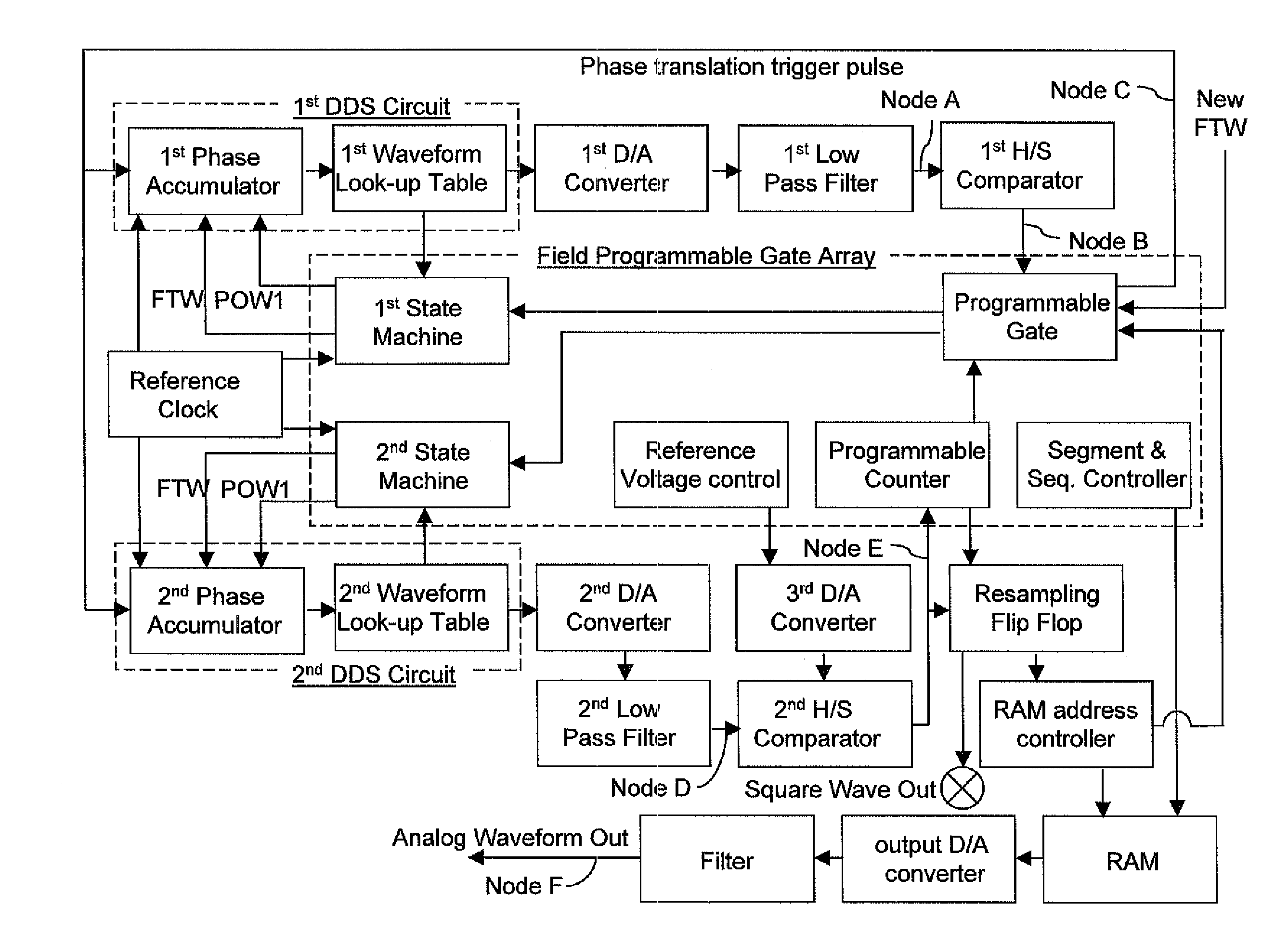
[0051]Referring to FIG. 3, an exemplary waveform generation circuit for a waveform generator according to the present invention comprises a first direct digital synthesis (DDS) circuit, a second DDS circuit, a field programmable gate array (FPGA), a random access memory (RAM) storing an arbitrary waveform, and a RAM address controller.

[0052]The first DDS circuit includes a first phase accumulator and a first waveform look-up table, which outputs a first digital output signal based on a first phase output from the first phase accumulator. The first digital output signal is herein refereed to as a frequency-tunable first DDS output signal, which is the output signal of the first DDS circuit. Likewise, the second DD...


PUM


Abstract

Jitterless transition of the programmable clock waveform is generated employing a set of two coupled direct digital synthesis (DDS) circuits. The first phase accumulator in the first DDS circuit runs at least one cycle of a common reference clock for the DDS circuits ahead of the second phase accumulator in the second DDS circuit. As a phase transition through the beginning of a phase cycle is detected from the first phase accumulator, a first phase offset word and a second phase offset word for the first and second phase accumulators are calculated and loaded into the first and second DDS circuits. The programmable clock waveform is employed as a clock input for the RAM address controller. A well defined jitterless transition in frequency of the arbitrary waveform is provided which coincides with the beginning of the phase cycle of the DDS output signal from the second DDS circuit.

Description

STATEMENT REGARDING FEDERALLY SPONSORED RESEARCH OR DEVELOPMENT[0001]This invention was made with government support under Contract No. DE-AC05-00OR22725 awarded by the U.S. Department of Energy. The government has certain rights in this invention.FIELD OF THE INVENTION[0002]The present invention relates to electronic devices and electronic circuits, and more particularly to a high frequency resolution arbitrary waveform generator providing jitterless frequency stepping, and circuits for the same and methods of operating the same.BACKGROUND OF THE INVENTION[0003]High resolution arbitrary waveform generators, which are also referred to as function generators, are employed in electronic applications to provide an arbitrary waveform in the frequency range above 1 MHz. Agile high resolution arbitrary waveform generators provide fast switching of arbitrary waveforms, which may be advantageously employed to provide frequency stepping in electronic instrumentation.[0004]Direct Digital Synt...

Claims


Application Information

Patent Timeline
IPC IPC(8): H03B27/00
CPCG06F1/0328
Inventor REILLY, PETER T. A.KOIZUMI, HIDEYA
Owner UT BATTELLE LLC
Why Eureka
Try Eureka