
Variable valve actuator

a valve actuator and variable technology, applied in the direction of valve arrangement, machines/engines, mechanical equipment, etc., can solve the problems of difficult to easily apply the valves to existing mass-produced engines, difficult to change the valve train depending on engine operation, and inability to more efficiently adjust the lift time of the valve, etc., to achieve the effect of adjusting the lift time and the lift distance, easy to adjust the lift time of each valve, and excellent applicability to the engin

Inactive Publication Date: 2009-10-01
HYUNDAI MOTOR CO LTD +1
View PDF6 Cites 5 Cited by
  • Summary
  • Abstract
  • Description
  • Claims
  • Application Information

AI Technical Summary

Benefits of technology

[0017]Embodiments of the present invention has been made to solve the foregoing problems with the prior art, and therefore the present invention is directed to a variable valve actuator, capable of adjusting the lift time and the lift distance of each valve without changing positions of the drive cams and the camshaft, and more stably adjusting the lift time of each valve, and simplifying internal configuration.
[0026]According to an exemplary embodiment of the present invention, the variable valve actuator can adjust a lift time and a lift distance of each valve without changing positions of the drive cams and the camshaft, and more easily adjust the lift time of each valve, and have very excellent applicability to the engine due to simple internal configuration.

Problems solved by technology

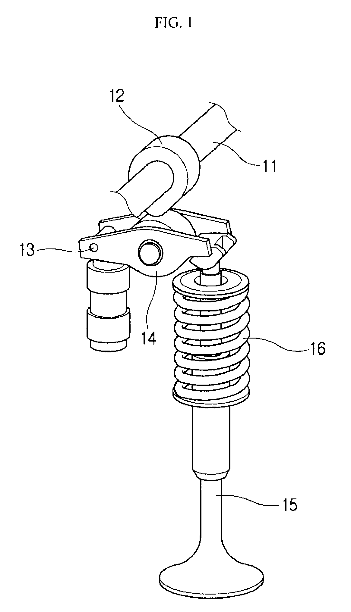
However, this ordinary valve train makes a single degree-of-freedom system motion by motion of the cam, so that it is impossible to change the valve train depending on engine operation conditions such as high-speed and low-speed engine operation conditions.
However, these variable valve actuators must change positions of the drive cams 12 and the camshaft 11, so that it is difficult to easily apply them to existing mass-produced engines.
Further, these variable valve actuators are designed to merely adjust the lift time of the valve 15 by increasing or decreasing the lift distance of the valve 15, so that it is impossible to more efficiently adjust the lift time of the valve 15.

Method used


Image

  • Variable valve actuator
  • Variable valve actuator
  • Variable valve actuator

Examples


Embodiment Construction

[0033]The present invention will now be described more fully hereinafter with reference to the accompanying drawings, in which exemplary embodiments thereof are shown. In the following description of the present invention, a detailed description of known functions and components incorporated herein will be omitted when it may make the subject matter of the present invention rather unclear.

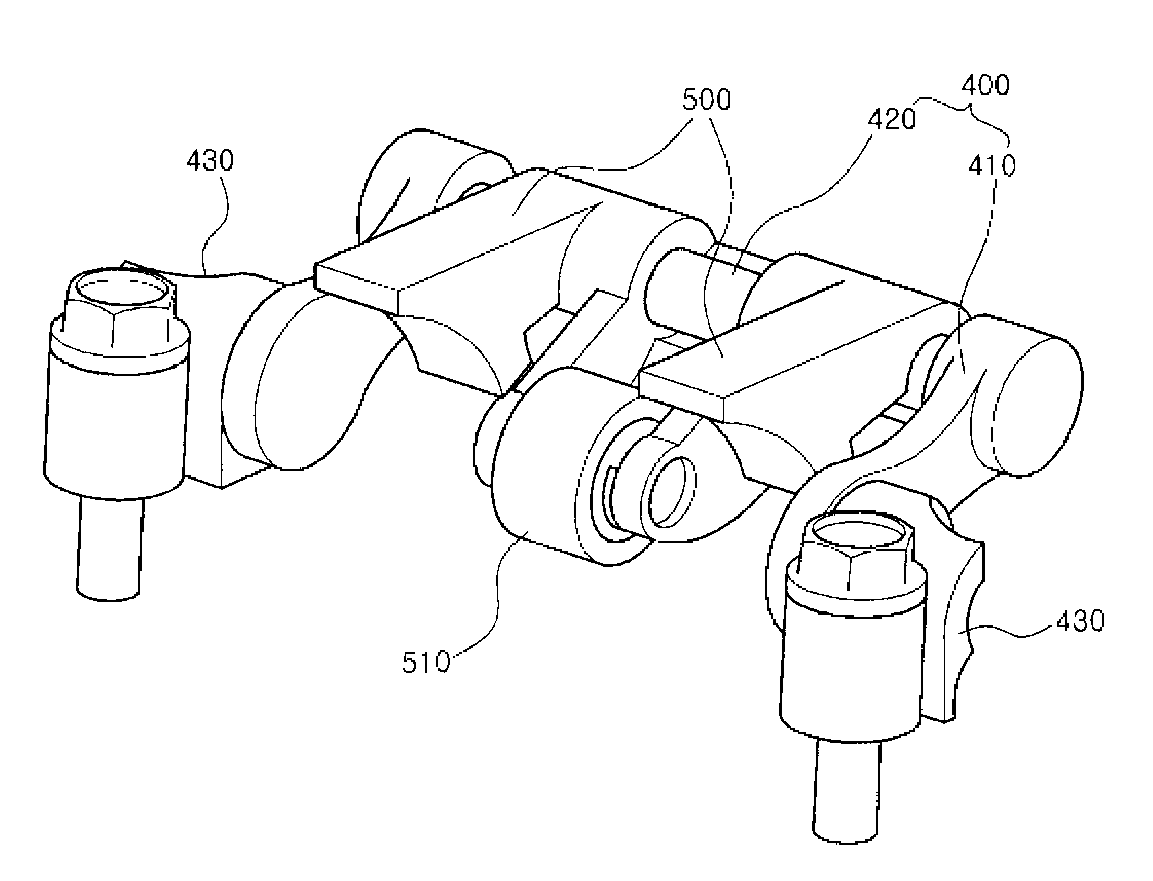
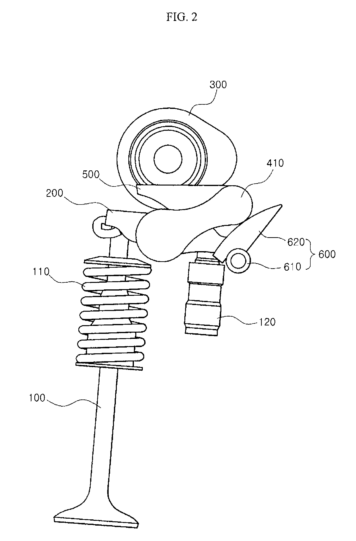
[0034]FIG. 2 is a side view illustrating a variable valve actuator according to an exemplary embodiment of the present invention. FIG. 3 is a perspective view illustrating the state in which a variable valve actuator is mounted on an engine according to an exemplary embodiment of the present invention. FIG. 4 is a perspective view illustrating a variable valve actuator according to an exemplary embodiment of the present invention.

[0035]As illustrated in FIGS. 2, 3 and 4, the variable valve actuator according to an exemplary embodiment of the present invention functions to press rocker arms 200 by u...


PUM


Abstract

A variable valve actuator presses rocker arms using force transmitted from a drive cam to open / close valves of an engine, and includes a swing arm, which is pivotably coupled to the engine on a first side thereof, and at least two pressing means, which come into contact with the rocker arms on first sides thereof, are pivotably coupled to a second side of a swing arm on second sides thereof, and press the rocker arms when pressed by the drive cam. Thereby, the variable valve actuator can adjust a lift time and a lift distance of each valve without changing positions of the drive cams and the camshaft, and more easily adjust the lift time of each valve, and have very excellent applicability to the engine due to simple internal configuration.

Description

CLAIM OF PRIORITY[0001]This application claims the benefit of Korean Patent Application No. 10-2008-0030295 filed on Apr. 1, 2008, in the Korean Intellectual Property Office, the disclosure of which is incorporated herein by reference.BACKGROUND OF THE INVENTION[0002]1. Field of the Invention[0003]The present invention relates to a variable valve actuator and, more particularly, to a variable valve actuator, in which the lift time and the lift distance of a valve are varied according to the low- / high-speed operating range of an engine.[0004]2. Description of the Related Art[0005]As for an engine, a camshaft is rotated by a rotating force transmitted from a crank shaft, and an intake valve and an exhaust valve are reciprocated up and down with regular timing by cams of the camshaft. Thereby, intake air is supplied to a combustion chamber, and then combustion gas is exhausted. In this process, a fuel-air mixture is compressed and exploded to generate power.[0006]In this manner, a seri...

Claims


Application Information

Patent Timeline
IPC IPC(8): F01L1/34
CPCF01L13/0021F01L1/267F01L1/18F01L13/00
Inventor LEE, JONG WON
Owner HYUNDAI MOTOR CO LTD
Learn More