
System and method for controlling an electronic device

Inactive Publication Date: 2009-09-17
SHENZHEN FUTAIHONG PRECISION IND CO LTD +1
View PDF13 Cites 48 Cited by
  • Summary
  • Abstract
  • Description
  • Claims
  • Application Information

AI Technical Summary

Benefits of technology

[0005]However, display screens of most electronic devices use liquid crystal display (LCD) technology, increasing device costs. Moreover, stylus operation on the LCD touch panel can deteriorate surface integrity thereof, resulting in reduction of lifespan of the LCD touch panel.

Problems solved by technology

However, display screens of most electronic devices use liquid crystal display (LCD) technology, increasing device costs.
Moreover, stylus operation on the LCD touch panel can deteriorate surface integrity thereof, resulting in reduction of lifespan of the LCD touch panel.

Method used


Image

  • System and method for controlling an electronic device
  • System and method for controlling an electronic device
  • System and method for controlling an electronic device

Examples


Embodiment Construction

[0011]All of the processes described may be embodied in, and fully automated via, functional code modules executed by one or more general purpose computers or processors. The code modules may be stored in any type of computer-readable medium or other storage device. Some or all of the methods may alternatively be embodied in specialized computer hardware or electronic apparatus.

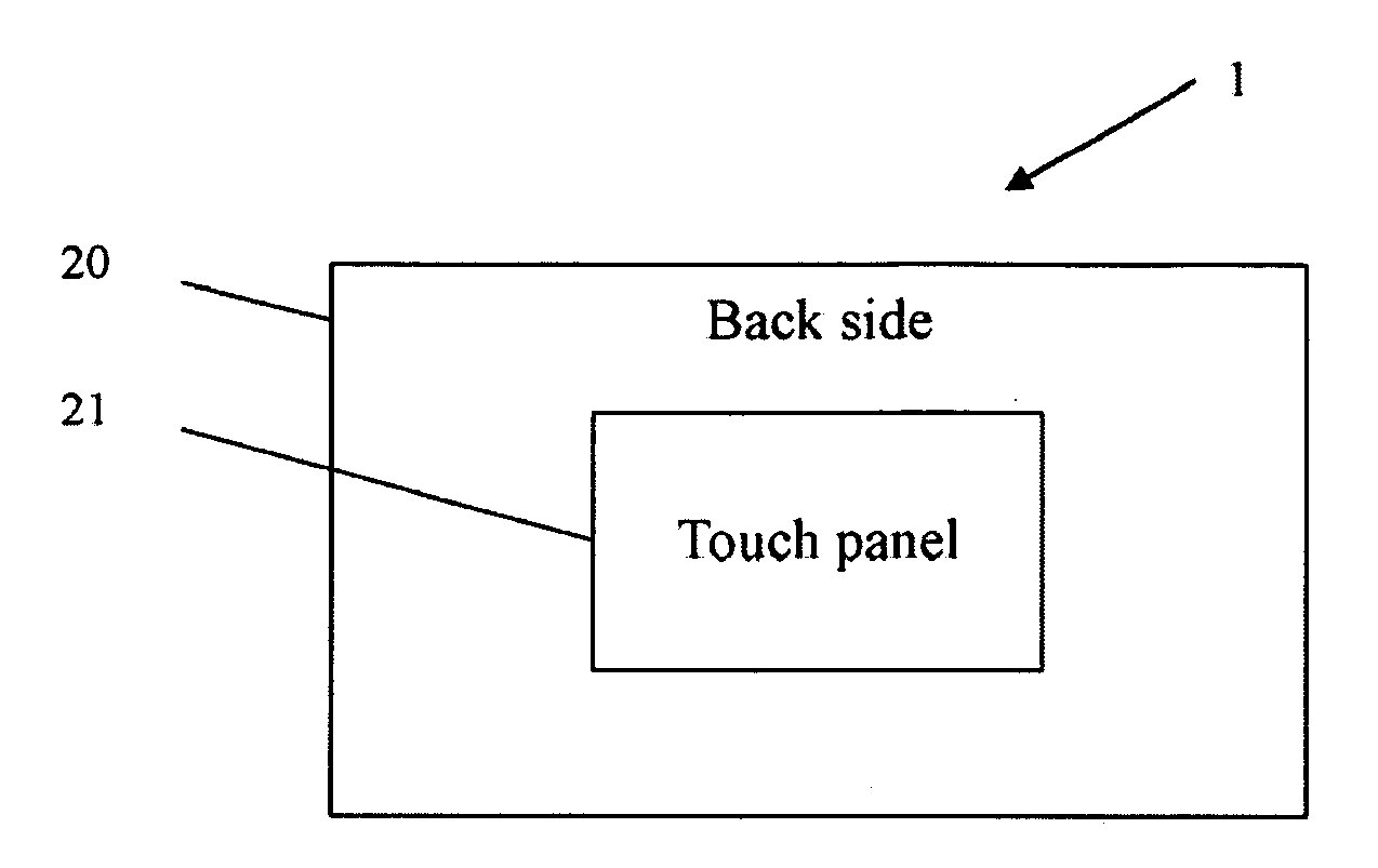
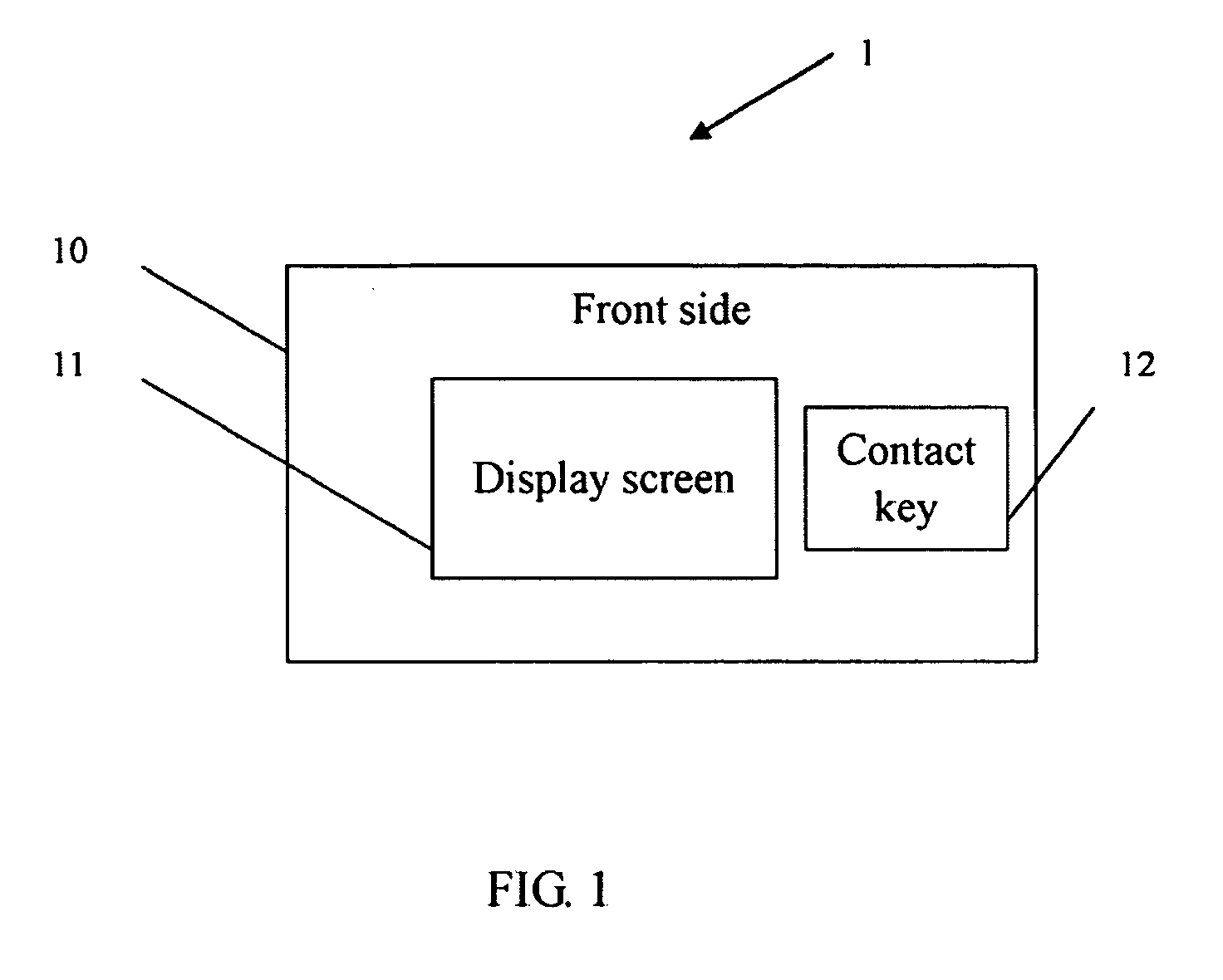
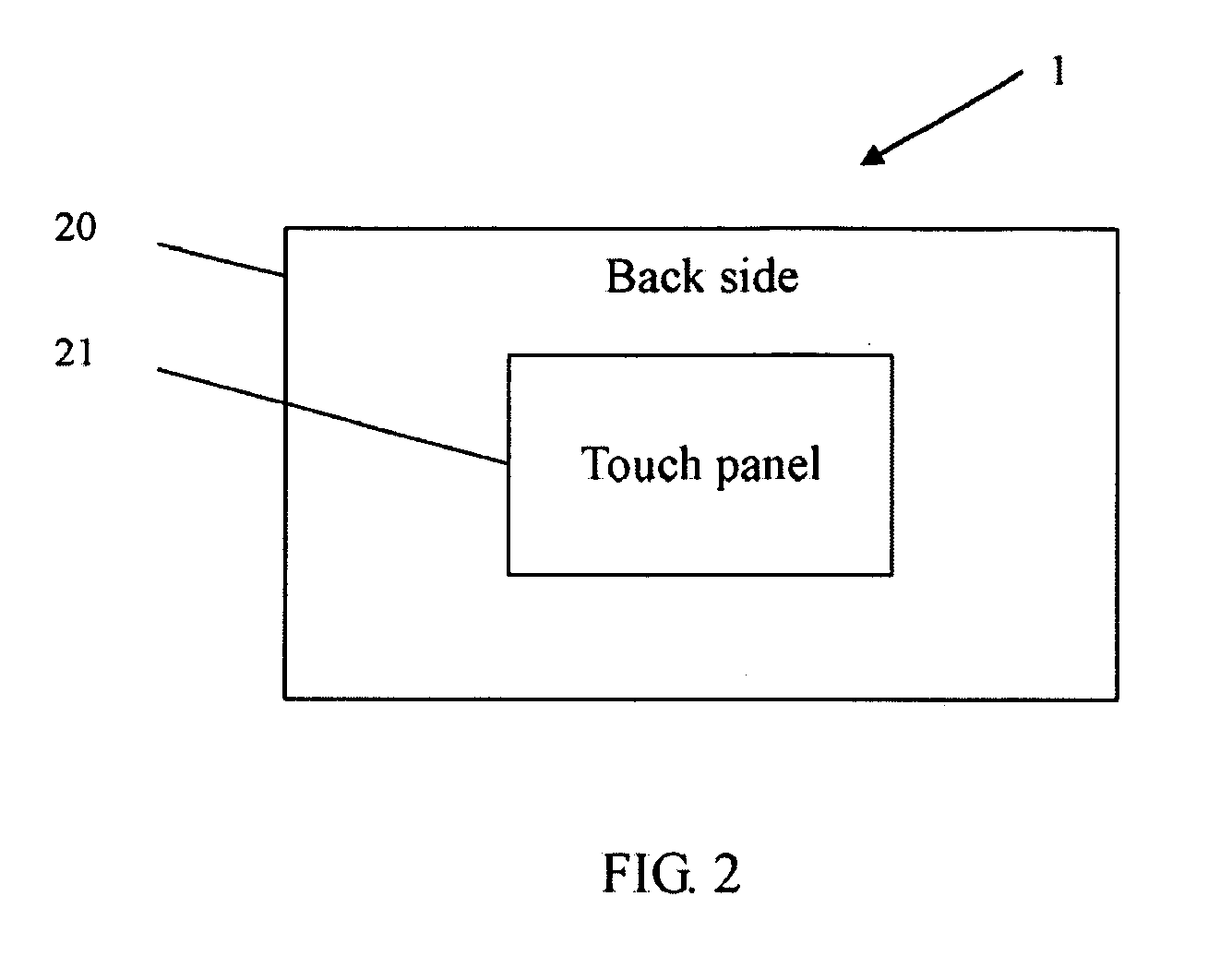
[0012]FIG. 1 is a block diagram of one embodiment of a front side 10 of an electronic device 1. FIG. 2 is a block diagram of a back side 20 of the electronic device 1 in FIG. 1. The front side 10 of the electronic device 1 includes a display screen 11 and a contact key 12. The back side 20 of the electronic device 1 includes a touch panel 21. In this embodiment, the electronic device 1 is a portable electronic device, but may alternatively be a query terminal device, a point of sale (POS) device, a retail cashier device, an automatic teller machine (ATM), or other devices without limiting the scope of the dis...


PUM


Abstract

An electronic device includes a display screen and a contact key on a front side and a touch panel on a back side. The electronic device further includes a system configured for controlling the electronic device via contact on the touch panel and contact of the contact key, and displaying corresponding actions via a cursor on the display screen.

Description

BACKGROUND[0001]1. Field of the Invention[0002]Embodiments of the present disclosure are related to device controlling systems and methods, and particularly to a system and method for controlling an electronic device.[0003]2. Description of Related Art[0004]Presently, electronic devices, such as personal digital assistants, global positioning system (GPS) consoles, or personal computers (PC), can use touch screens and display screens to allow input and output of data via contact therewith, increasing convenience for the user.[0005]However, display screens of most electronic devices use liquid crystal display (LCD) technology, increasing device costs. Moreover, stylus operation on the LCD touch panel can deteriorate surface integrity thereof, resulting in reduction of lifespan of the LCD touch panel.[0006]What is needed, therefore, is a system and method for controlling an electronic device to overcome the described limitations.BRIEF DESCRIPTION OF THE DRAWINGS[0007]FIG. 1 is a block...

Claims


Application Information

Patent Timeline
IPC IPC(8): G06F3/041
CPCG06F3/0488G06F1/1626
Inventor CHEN, XIANG-YU
Owner SHENZHEN FUTAIHONG PRECISION IND CO LTD
Learn More