
Method for real-time learning of actuator transfer characteristics

Active Publication Date: 2009-09-03
DELPHI TECH IP LTD
View PDF18 Cites 26 Cited by
  • Summary
  • Abstract
  • Description
  • Claims
  • Application Information

AI Technical Summary

Benefits of technology

[0007]An advantage of a first aspect of the invention, in a fluid pressure control embodiment, is that it provides a control system that can accommodate in a solenoid-operated valves having an increased amount of variation, due to a dynamic learning feature that adjusts a default transfer characteristic to an actual, measured transfer characteristic. This improvement allows for a more accurate forward control signal, reducing the output error, which allows increased effectiveness of any closed loop controller. It should be understood that this aspect is not limited to a pressure control embodiment, and may be applied more generally to any device having an input-versus-output transfer characteristic, for example, a solenoid whose output is a position, a DC wheel motor whose output is a rotational speed in RPM (e.g., in the case of an electric vehicle), or a variable effort steering actuator where the actuator output would be the steering column stiffness (calculated from position and / or torque sensors).
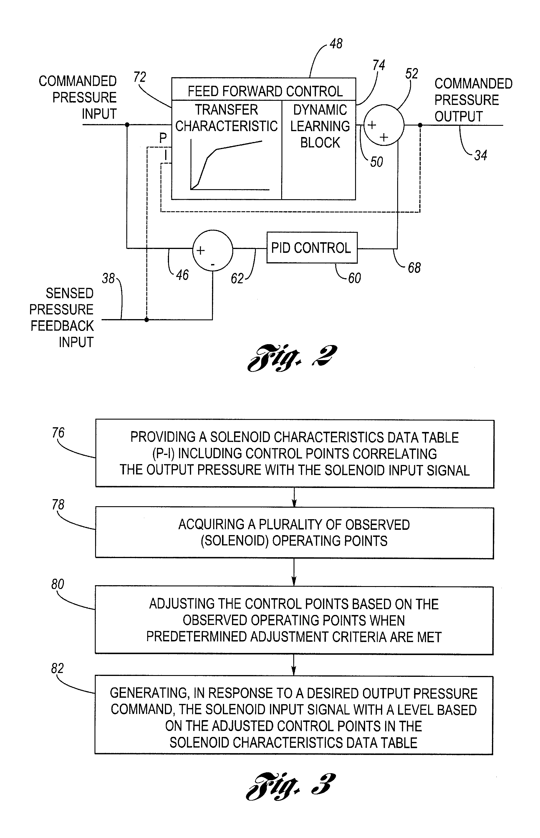
[0010]However, in the second aspect, a particular method is provided for performing the adjusting step described above. The method is suitable for use in a system having a solenoid-operated fluid valve that has an output hydraulic pressure which varies in accordance with a solenoid input signal. The method of dynamically adjusting a transfer characteristic of the solenoid-operated valve includes a number of steps. The first step involves providing a data table including control points correlating the output pressure with the input signal to thereby define the transfer characteristic, wherein consecutive control points in the table define respective ranges. The next step involves acquiring observed operating points based on observed input signal levels and the resulting measured output pressure levels. The next step involves storing the observed operating points in a plurality of circular buffers, each buffer configured to store a predetermined number of observed operating points, each buffer also being associated with one of the plurality of ranges mentioned above. The next step involves adjusting the control points based on the observed operating points when predetermined adjustment criteria is met. The final step involves selectively re-aligning unadjusted control points (consistent with the original, default values for the control points). The ability to adjust control points based on observed data occurring in a limited range (i.e., as reflected by data in just one of the circular buffers) enables effective updating of the transfer characteristic with only partial data. Moreover, selectively realigning the remaining unadjusted control points produces end-to-end consistency in the transfer characteristic.

Problems solved by technology

The system variation could be due to a supply limitation.
For example, the system may learn of something obstructing the movement of a position actuator or there may not be enough energy available to drive the electric vehicle's wheels to the commanded speed.

Method used


Image

  • Method for real-time learning of actuator transfer characteristics
  • Method for real-time learning of actuator transfer characteristics
  • Method for real-time learning of actuator transfer characteristics

Examples


Embodiment Construction

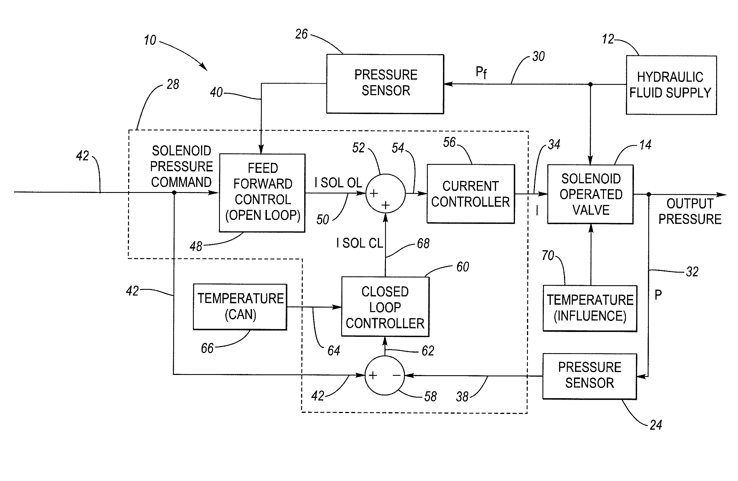
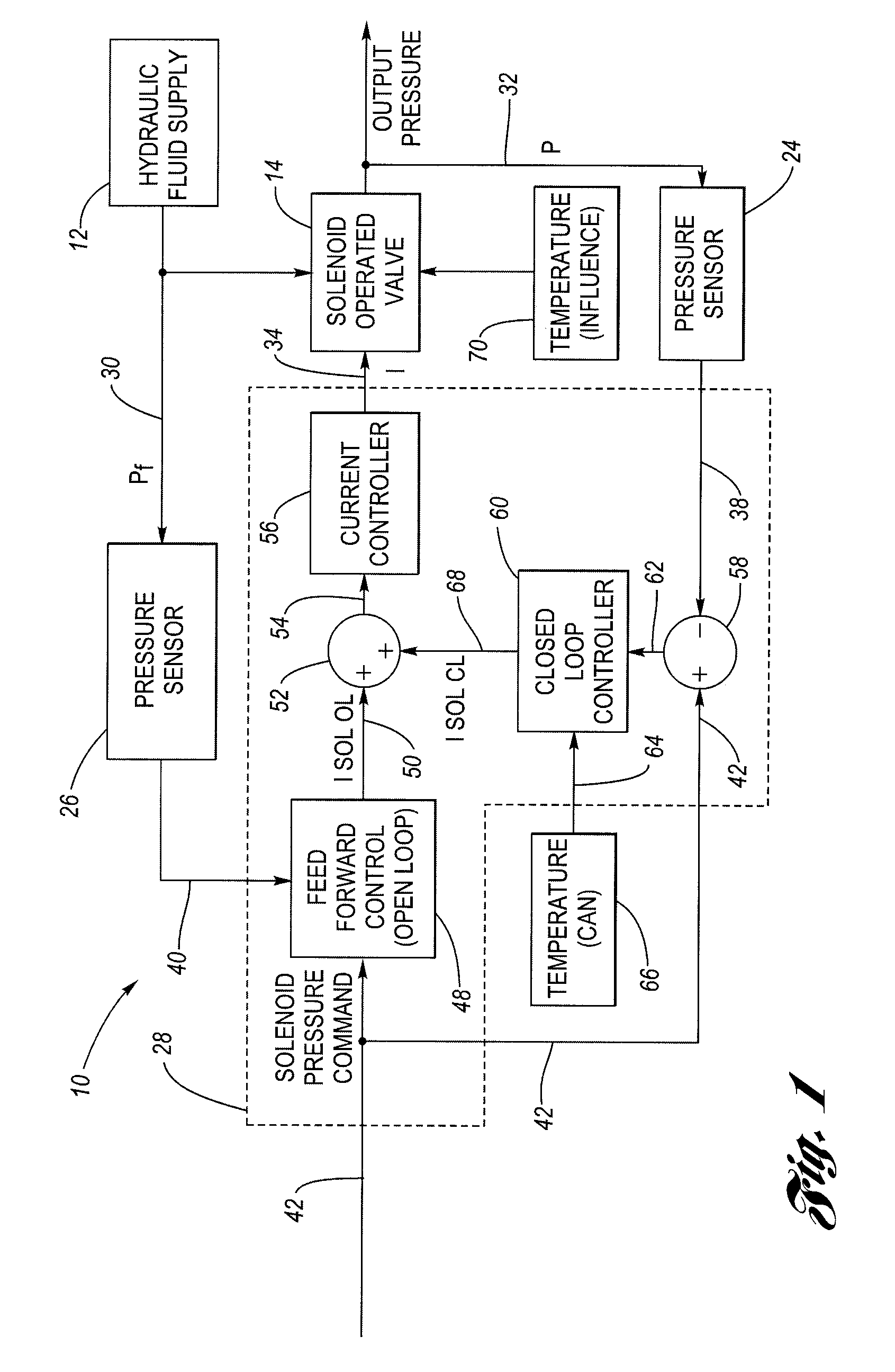
[0023]Referring now to the drawings wherein like reference numerals are used to identify identical components in the various views, FIG. 1 is a block diagram of an environment in which both aspects of the invention may be practiced. FIG. 1 shows a control system 10 for closed-loop hydraulic fluid pressure control. The system 10 includes a fluid supply 12 and is configured generally to control an output pressure of a solenoid-operated valve 14. While the invention will be illustrated in the context of FIG. 1, it should be understood that this is exemplary only and not limiting in nature. One of ordinary skill in the art will recognize a variety of additional or alternative useful applications of the invention. For example only, the invention may be suitable for use in controlling a clutch pressure in an automatic speed change transmission for an automotive vehicle. Additionally, more broadly, the invention may be applied to any actuator having an input-versus-output transfer characte...


PUM


Abstract

In a pressure control system having a solenoid-operated fluid valve that has an output hydraulic pressure which varies in accordance with a solenoid input signal, a dynamic learning block is configured to adjust the initial, default values for control points stored in a pressure-current (P-I) data table based on observed (measured) operating points that reflect the solenoid's actual transfer characteristic. A feed forward control block is configured to generate the solenoid input signal having a level based on the adjusted control points in the data table, which improves the accuracy of the solenoid input signal. An adjustment method uses a plurality of circular buffers each configured to store observed operating points falling within a respective range, and provides a mechanism to allow adjustment of the control points based on only partial data.

Description

TECHNICAL FIELD [0001]The invention relates generally to improvements in fluid pressure controls and, more particularly, to a system and method involving dynamic learning of solenoid P-I curves suitable for use in closed loop pressure controls.BACKGROUND OF THE INVENTION [0002]Hydraulic fluid controls can be found in a variety of automotive applications such as automatic speed change transmissions as well as others. In these applications, it is often desirable to control the pressure of the hydraulic fluid. For example, in a common configuration, an electronic transmission control unit (TCU) for an automatic speed change transmission is configured to generate electrical signals that control solenoids, which in turn results in the control of fluid flow as well as the pressure in various hydraulic fluid lines. The pressure in a hydraulic fluid line can be used to control various other elements including, for example, a hydraulically-actuated clutch for the engagement of individual gea...

Claims


Application Information

Patent Timeline
IPC IPC(8): G06F19/00
CPCF16K37/0091
Inventor KRAENZLEIN, JEREMY J.ZHENG, QUAN
Owner DELPHI TECH IP LTD
Learn More