
Control method for industrial vehicle and industrial vehicle

a technology for industrial vehicles and control methods, applied in the direction of battery/cell propulsion, process and machine control, instruments, etc., can solve the problems of significant fluctuation of battery voltage, inability to determine accurate soc, and inability to accurately control the soc, so as to prevent the reduction of battery efficiency and reduce the battery efficiency. , the effect of preventing an excessively large charge amoun

Active Publication Date: 2009-09-03
NIPPON YUSOKI
View PDF9 Cites 37 Cited by
  • Summary
  • Abstract
  • Description
  • Claims
  • Application Information

AI Technical Summary

Benefits of technology

[0024]According to the control method for an industrial vehicle and the industrial vehicle of the present invention, effects are exhibited in which the charge amount for the battery can be appropriately set by calculating the charge power that is necessary for supplying the determined charge amount, and adding the power that is necessary for charging to the power that is supplied by the engine.
[0025]According to the control method for an industrial vehicle and the industrial vehicle of the present invention, effects are exhibited in which the charge amount for the battery, which depends on the operating state such as the travel state and the load-handling state, can be appropriately set by switching between a charging mode and a discharging mode based on the traveling and load-handling states of the industrial vehicle.
[0026]According to the control method for an industrial vehicle and the industrial vehicle of the present invention, effects are exhibited in which the charge amount for the battery can be appropriately set by adjusting the charge amount based on the summed values of the operating time and the charge correction amounts. In particular, because the battery efficiency is reduced when the charge amount for the battery is large, a reduction in the battery efficiency can be prevented by preventing an excessively large charge amount by appropriately setting the charge amount for the battery.

Problems solved by technology

In the case in which the battery SOC is determined by using these methods, there is a problem in that the battery voltage fluctuates significantly while charging and while discharging, and thus determining an accurate SOC is not possible.
Furthermore, although the battery SOC can be determined by using the relationship between the battery voltage and the battery SOC, a battery voltage that fluctuates significantly takes time to return to the original voltage, as described above, and thus, there is a problem in that determining the correct battery SOC takes time.
In contrast, the battery SOC must be controlled so as to maintain predefined values while supplying to a vehicle the power that is necessary for travel operations and load-handling operations, and thus, there is a problem in that power control becomes necessary.

Method used


Image

  • Control method for industrial vehicle and industrial vehicle
  • Control method for industrial vehicle and industrial vehicle
  • Control method for industrial vehicle and industrial vehicle

Examples


first embodiment

[0045]Below, a forklift according to a first embodiment of the present invention will be explained with reference to FIG. 1 to FIG. 16.

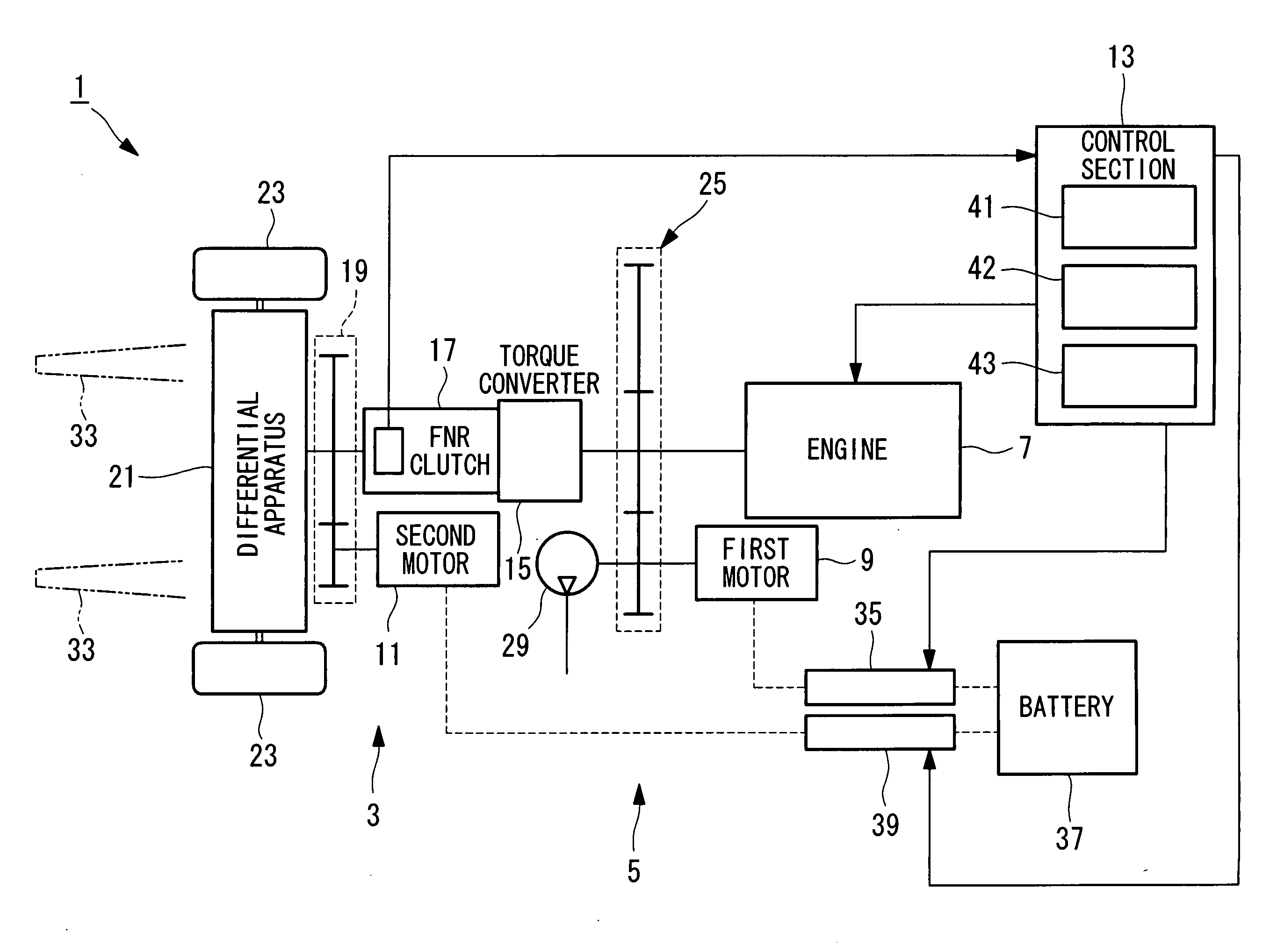
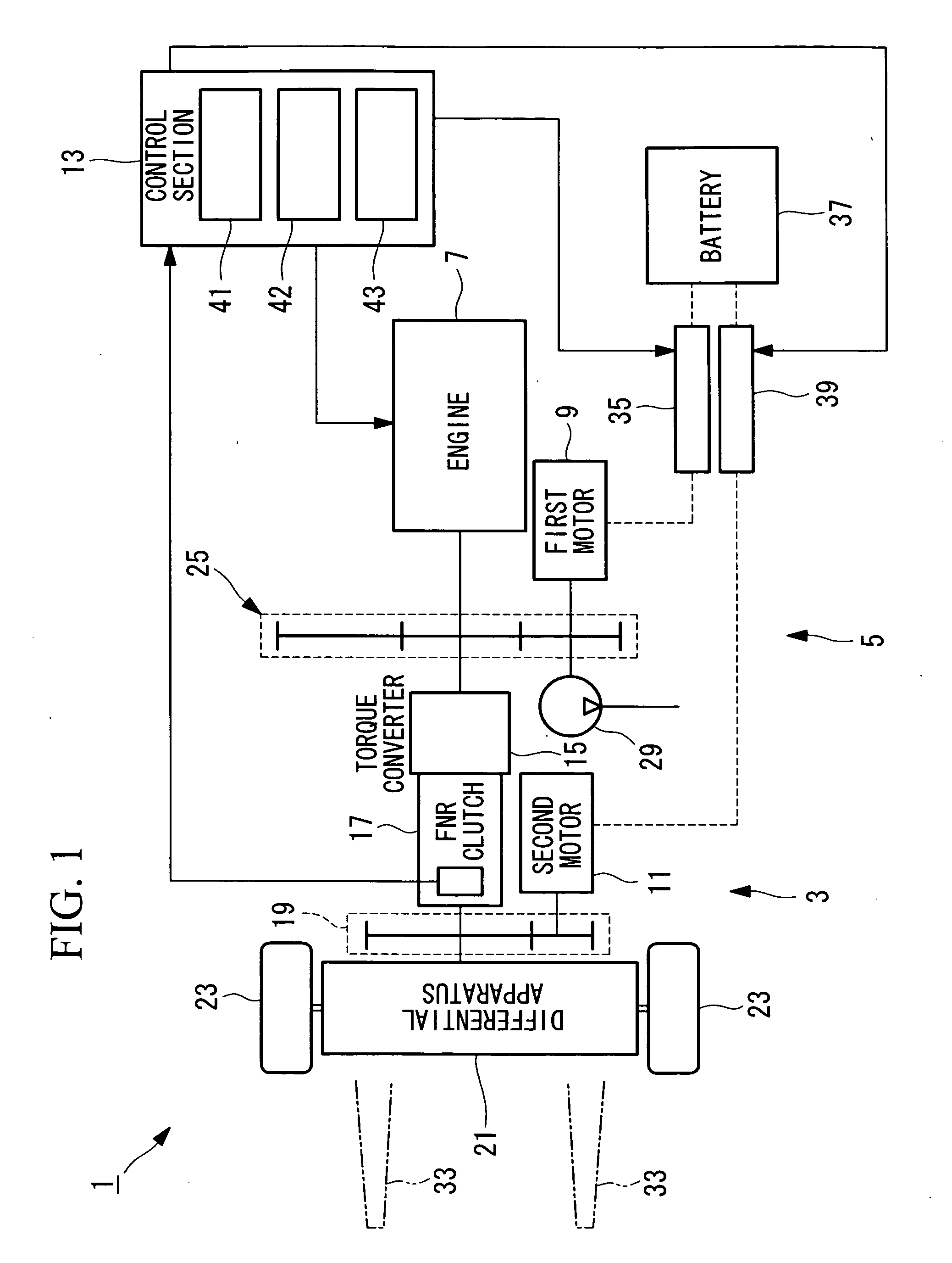
[0046]FIG. 1 is a drawing that shows the power train system of the forklift according to the present invention.

[0047]In the present embodiment, an application to a parallel forklift will be explained, the parallel forklift being a hybrid forklift (referred to hereinbelow as a “forklift”) that uses an engine and motors as power sources, and uses not only the motor power but also the engine power for traveling and load-handling.

[0048]As shown in FIG. 1, the forklift (industrial vehicle) 1 is provided with a travel section 3 that carries out travel, a load-handling section 5 that carries out load-handling, an engine 7 and a first motor (motor) 9 that supply power to at least one of the travel section 3 and the load-handling section 5, a second motor (motor) 11 that supplies power to the travel section 3, and a control section 13 that calculates the powe...

second embodiment

[0187]Next, a second embodiment of the present invention will be explained with reference to FIG. 17 and FIG. 18.

[0188]The basic structure of the forklift of the present embodiment is identical to that of the first embodiment, and only the control in the charge correction amount determining section differs from that in the first embodiment. Thus, in the present embodiment, only the control in the charge correction amount determining section will be explained with reference to FIG. 17 and FIG. 18, and the explanation of the other aspects of the control and the like will be omitted.

[0189]FIG. 17 is a block diagram for explaining the control in the charge correction amount determining section in the present embodiment.

[0190]Note that identical reference numerals are appended to structural elements that are identical to those of the first embodiment, and the explanations thereof will be omitted.

[0191]As shown in FIG. 17, the charge correction amount determining section 171 is provided w...


PUM


Abstract

A control method for an industrial vehicle can appropriately set a charge amount for a battery, and an industrial vehicle are provided. The control method includes an estimation step that estimates the charge rate of a battery by calculating the current that is charged to the battery and the current that is discharged from the battery; a charge amount determining step that determines the charge amount of the battery based on the estimated charge rate; a correction amount determining step that determines the charge power that is necessary for motors to generate the determined charge amount as a correction amount for the power that is supplied by the engine; and an addition step that adds the charge power to the supplied power of the engine that has been determined based on the state of the traveling and load-handling.

Description

BACKGROUND OF THE INVENTION[0001]1. Field of the Invention[0002]The present invention relates to a control method for an industrial vehicle, and to an industrial vehicle.[0003]This application is based on Japanese Patent Application No. 2008-051053, the content of which is incorporated herein by reference.[0004]2. Description of Related Art[0005]Generally, in a hybrid system that combines an engine and a motor, a battery is widely used as a power source (refer, for example, to Japanese Unexamined Patent Application, Publication No. 2000-313600).[0006]Among such batteries, the battery charge rate (below, the battery charge is referred to as the “battery SOC” (State of Charge)) must be controlled in those that are used in an HEV (Hybrid Electric Vehicle), and a variety of methods for controlling the battery SOC in hybrid systems have been proposed (refer, for example, to Japanese Unexamined Patent Application, Publication No. 2005-012902).[0007]Specifically, in the case in which the b...

Claims


Application Information

Patent Timeline
IPC IPC(8): B60W10/26B60W20/00B60K6/28B60L50/16
CPCB60K1/02Y02T10/7077B60L11/123B60L11/14B60L2200/42B60L2260/42B60W10/06B60W10/08B60W10/26B60W20/00B60W2510/244B60W2710/0677B60W2710/086B60Y2200/15Y02T10/6217Y02T10/6286Y02T10/7005B60L1/20Y02P90/60B60L50/61B60L50/16Y02T10/62Y02T10/7072Y02T10/70B60W20/13
Inventor KUBOTA, YUTAKAAKAKI, TOMOHIROFUTAHASHI, KENSUKE
Owner NIPPON YUSOKI
Learn More