
Turbojet compressor

a compressor and turbojet technology, applied in the direction of machines/engines, mechanical equipment, liquid fuel engines, etc., can solve the problems of affecting reducing the compression efficiency of the compressor, and reducing the aerodynamic behavior of the blade root section, so as to increase the compression and pumping efficiency of the low-pressure compressor

Active Publication Date: 2009-07-30
SN DETUDE & DE CONSTR DE MOTEURS DAVIATION S N E C M A
View PDF4 Cites 17 Cited by
  • Summary
  • Abstract
  • Description
  • Claims
  • Application Information

AI Technical Summary

Benefits of technology

[0008]A main object of the present invention is thus to mitigate such drawbacks by proposing a fan shroud shape that makes it possible to further increase the compression and pumping efficiency of the low-pressure compressor of a turbojet.
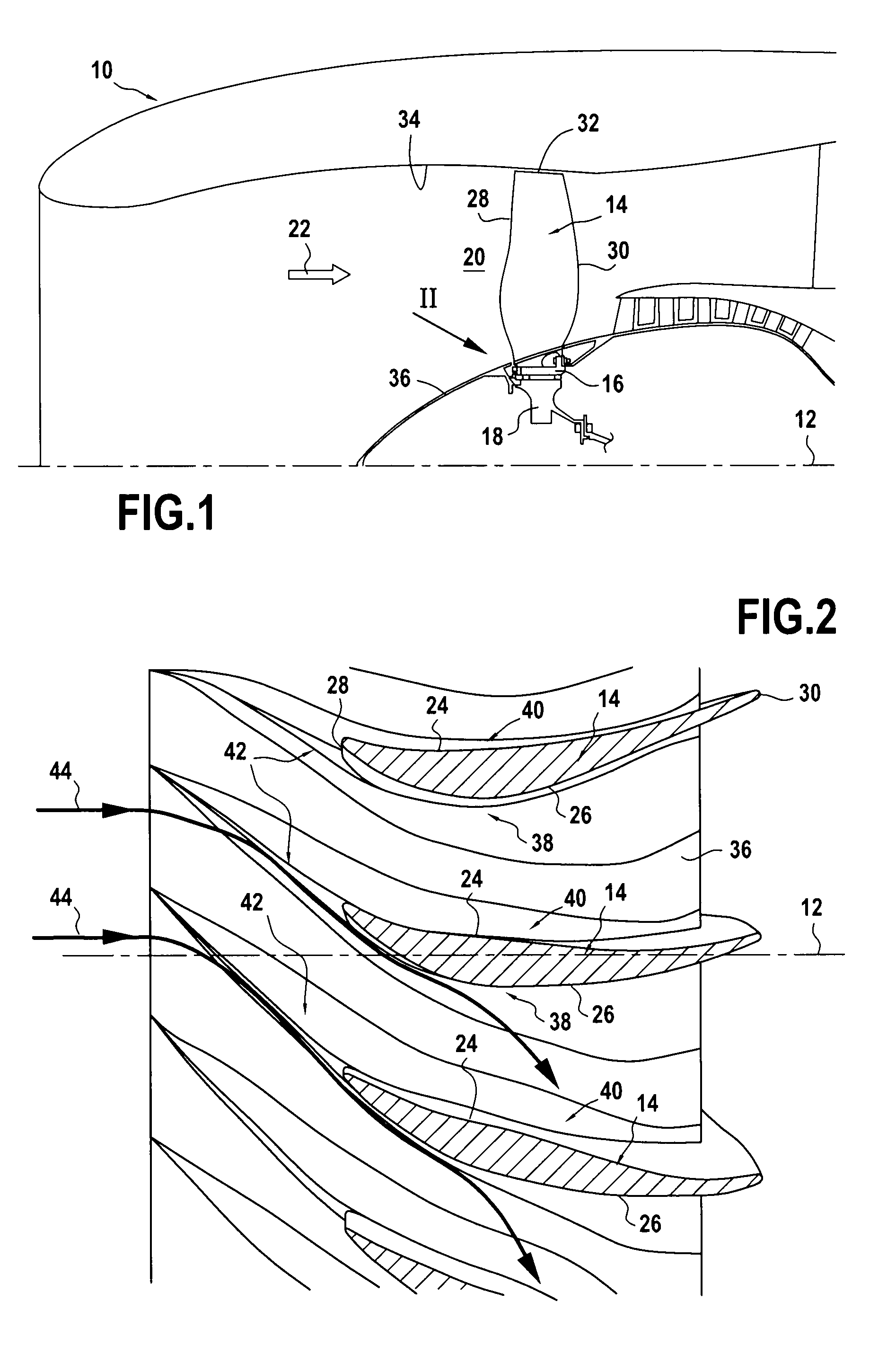
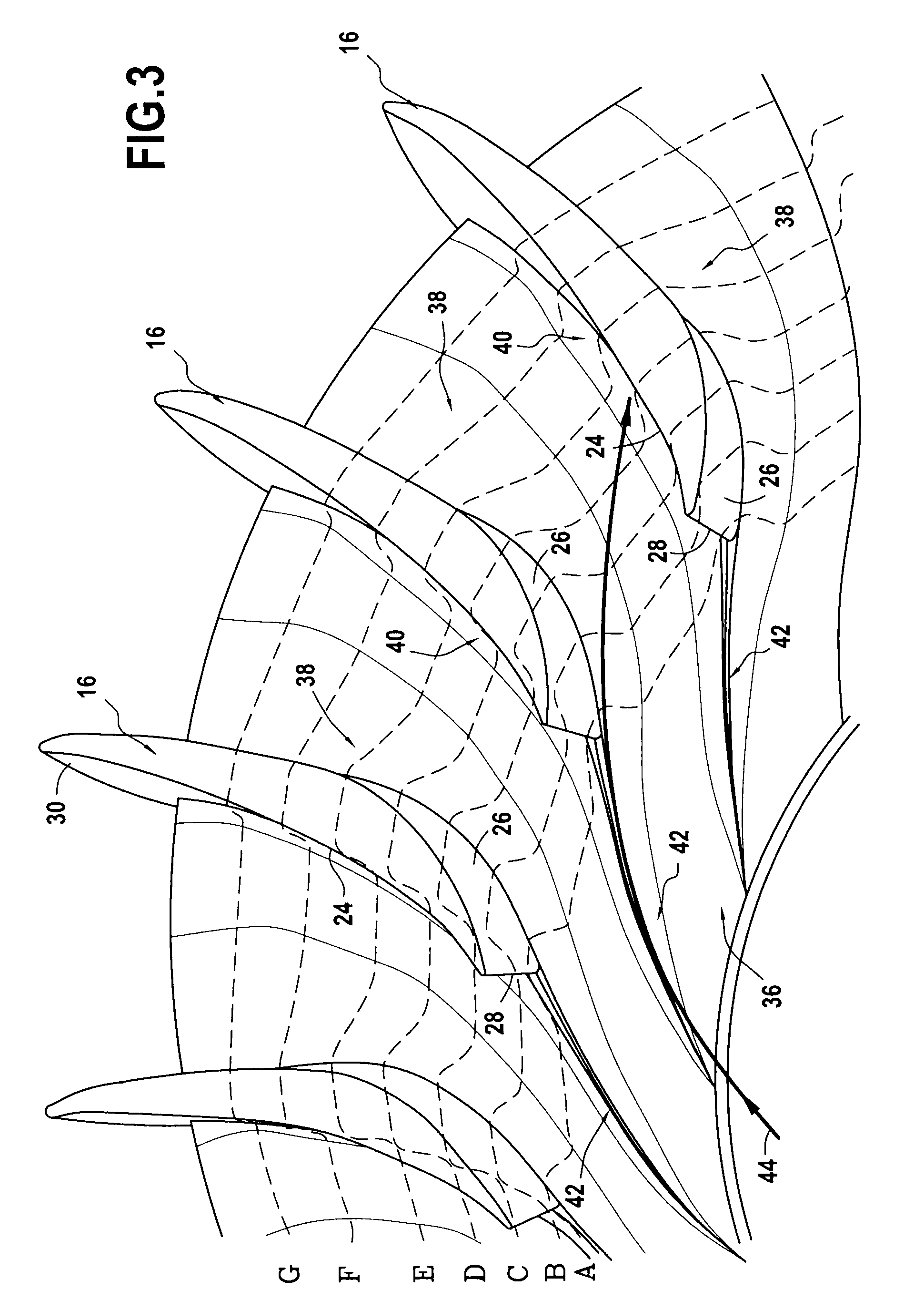
[0014]Because of the presence of the projection upstream from each blade root, the gas stream entering the compressor is forced to go round the blade root by passing mainly via the suction-side thereof (as opposed to via its pressure-side). The gas stream is then accelerated by suction and subsequently deflected towards the pressure-side surface of the adjacent blade because of the presence of the suction-side ramp. The compression and pumping efficiency of the compressor is thereby improved.
[0015]In an advantageous disposition, the inclination of the profile of each suction-side ramp decreases progressively from the leading edge to the trailing edge of each corresponding blade.

Problems solved by technology

Nevertheless, the fact that the duct is deepened in the shroud can have harmful consequences on the aerodynamic behavior of the blade root sections, in particular in the recompression zone situated on the suction-sides of the blades.

Method used


Image

  • Turbojet compressor
  • Turbojet compressor
  • Turbojet compressor

Examples


Embodiment Construction

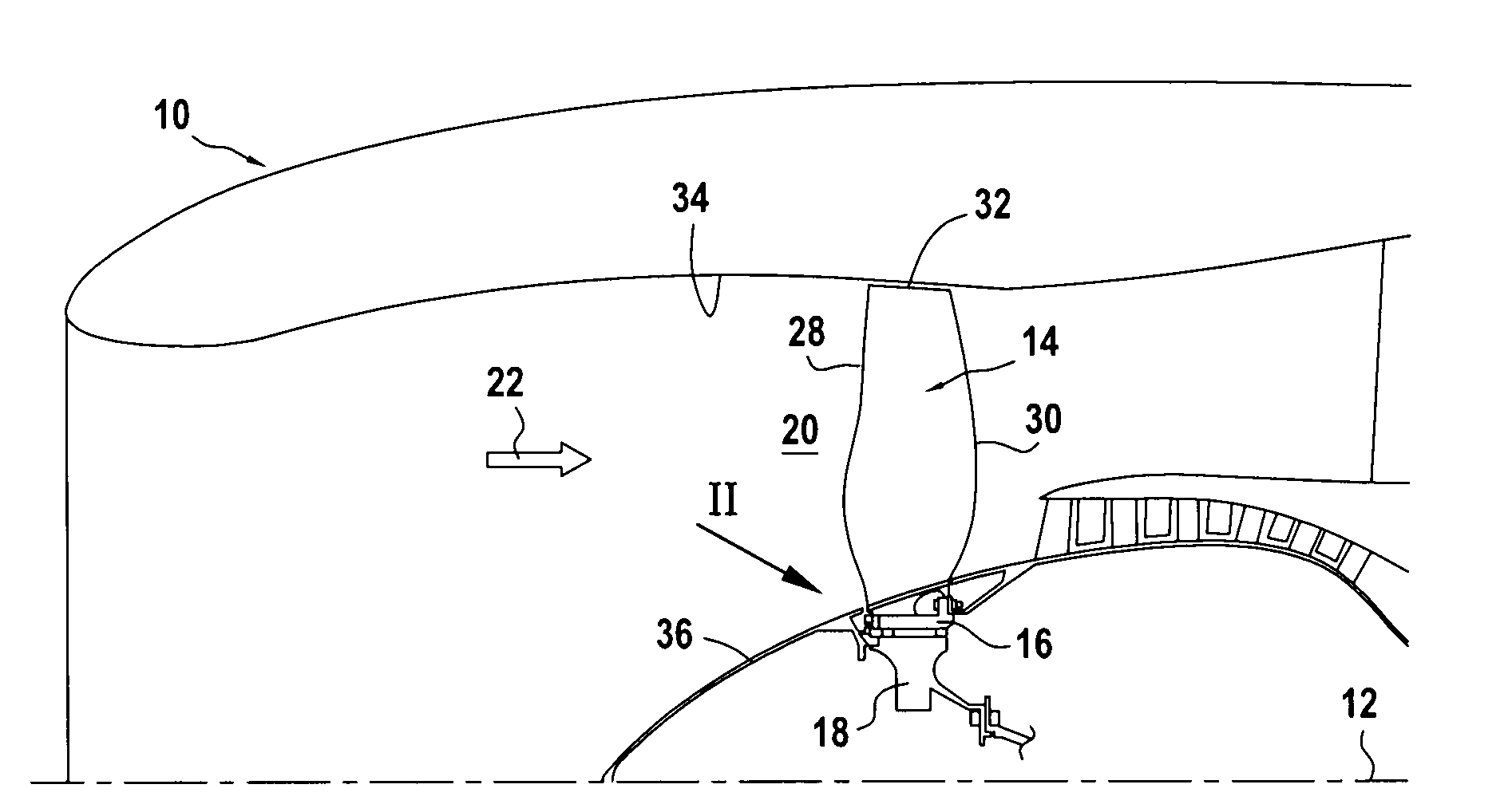
[0026]FIG. 1 shows a portion of a fan 10 (or low-pressure compressor) of a turbojet that is axially symmetrical about its longitudinal axis 12.

[0027]The fan 10 is situated at the inlet of the turbojet. It comprises a plurality of blades 14, each fastened in well-known manner via its root 16 to a disk 18 mounted to rotate about the longitudinal axis 12.

[0028]As shown in FIGS. 2 and 3, the fan blades 14 are regularly spaced apart from one another in a circumferential direction so as to define between them portions of an annular passage (or duct) 20 through which there flows a stream of air 22 passing through the fan 10.

[0029]In known manner, rotation of the disk 18 and of the fan blades 14 delivers energy to the air passing via the passage 20 of the fan and increases its pressure, while decreasing its relative flow speed.

[0030]Each blade 14 has a pressure-side surface 24 and a suction-side surface 26 that is circumferentially opposite its pressure-side surface (FIG. 2). The pressure-s...


PUM


Abstract

The invention relates to a turbojet compressor comprising a shroud and a plurality of blades, each fixed via its root to the shroud. Level with each blade root, the shroud presents a suction-side ramp and a pressure-side ramp extending from the trailing edge of the blade to beyond its leading edge. The pressure-side and suction-side ramps join together upstream from the leading edge of the blade to form a projection presenting a profile that is twisted about the axis of the shroud so as to force the gas stream flowing in each flow passage to go round the blade root essentially on the suction-side thereof, and the suction-side ramp presents a profile that is inclined relative to the outside surface of the shroud so as to deflect the gas stream flowing in the corresponding flow passage from the suction-side surface of the blade towards the pressure-side surface of the adjacent blade.

Description

FIELD OF THE INVENTION [0001]The present invention relates to the general field of turbojet compressors. More precisely, it relates to the fan (or low-pressure compressor) of a turbojet of the bypass type.[0002]In a bypass turbojet, air is compressed successively in a low-pressure compressor and in a high-pressure compressor, and it is then mixed with fuel and burnt in a combustion chamber. The energy extracted from the combustion gas is transformed into mechanical energy in a high-pressure turbine that serves to drive the high-pressure compressor, and by a low-pressure turbine that serves to drive the low-pressure compressor.[0003]In such a turbojet, the low-pressure compressor, also known as a fan, generally has a single stage of blades, each fixed via its root to a shroud that is itself movable in rotation about a longitudinal axis of the turbojet. An annular casing disposed concentrically around the shroud co-operates therewith to define an annular duct for passing the flow of a...

Claims


Application Information

Patent Timeline
IPC IPC(8): F01D11/08
CPCF01D5/143Y02T50/673F04D29/324Y02T50/60
Inventor AUBIN, STEPHANBELMONTE, OLIVIER
Owner SN DETUDE & DE CONSTR DE MOTEURS DAVIATION S N E C M A
Learn More