Automatic power management method

a power management and automatic technology, applied in the field of automatic power management, can solve problems such as link idling

Inactive Publication Date: 2009-07-23
MEDIATEK INC
View PDF2 Cites 33 Cited by
  • Summary
  • Abstract
  • Description
  • Claims
  • Application Information

AI Technical Summary

Problems solved by technology

But, before the outstanding commands have been completed, there might have some idleness in the link, such as waiting transmitting or receiving data or state information before the completion of the command.

Method used


Image

  • Automatic power management method
  • Automatic power management method
  • Automatic power management method

Examples


Embodiment Construction

[0025]The following description is of the best-contemplated mode of carrying out the invention. This description is made for the purpose of illustrating the general principles of the invention and should not be taken in a limiting sense. The scope of the invention is best determined by reference to the appended claims.

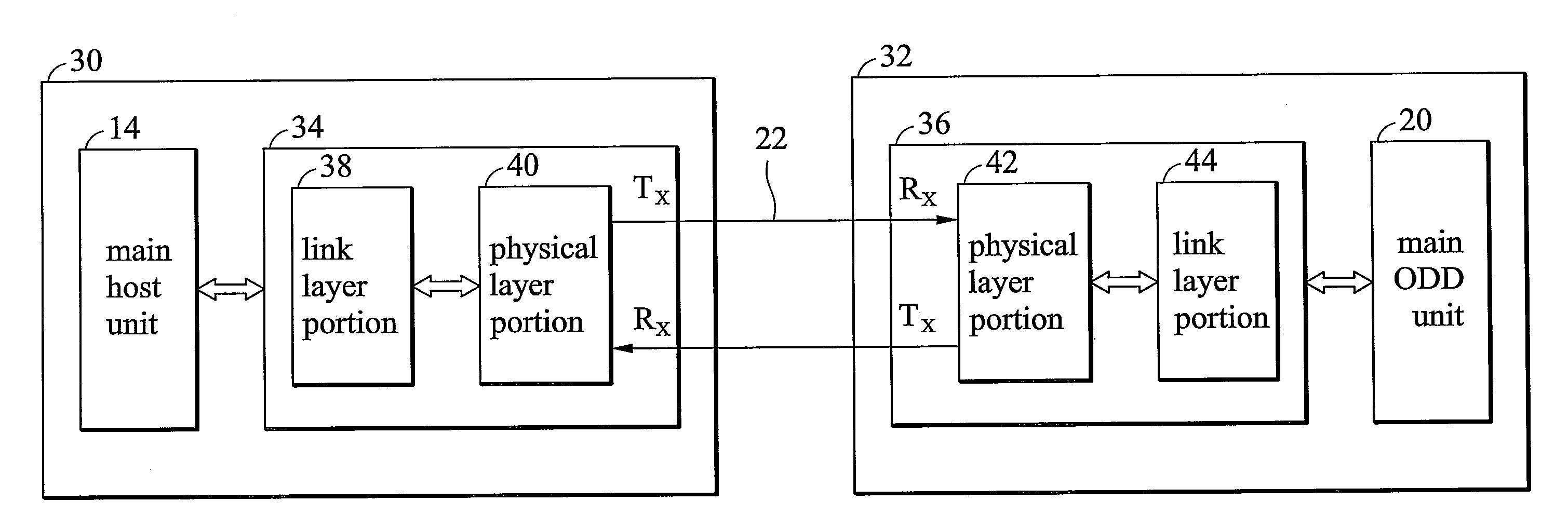
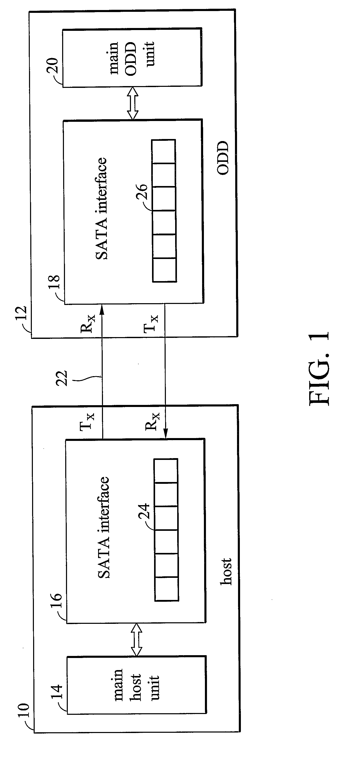
[0026]FIG. 1 is a block diagram illustrating a system with a host, such as a personal computer, and a storage device, such as an optical disc drive (ODD), communicating through a SATA bus according to an embodiment of the invention. Both of the host and the optical disc drive are SATA compatible devices. As shown, host 10 comprises a main host unit 14, a SATA interface 16, a transmitter module Tx for transmitting information and a receiver module Rx for receiving information and storage device 12 comprises a main ODD unit 20, a SATA interface 18, a transmitter module Tx for transmitting information and a receiver module Rx for receiving information. Both SATA interface...


PUM


Abstract

The application discloses methods applied to an electronic system capable of operating in a non power saving mode and a power saving mode. According to one of the methods, the idle time when the electronic system is idle in the non-power saving mode is measured. If the idle time equals or exceeds a mode entry time, the electronic system enters the power saving mode. The power down duration when the electronic system stays in the power saving mode is measured. The mode entry time is then modified based upon the power down duration.

Description

BACKGROUND OF THE INVENTION[0001]1. Field of the Invention[0002]The invention generally relates to power management and in particular to methods of automatic power management for devices integrating a serial bus interface.[0003]2. Description of the Related Art[0004]A SATA (serial advanced technology attachment) bus or a SAS (serial attached SCSI) bus, which is a serial bus that is expected replacing parallel interface in storage device, is primarily designed for data transfer between two SATA / SAS compatible device, such as a host (a computer for example) and a storage device (an optical disc drive for example). The SATA bus has at least three advantages over the parallel ATA bus, namely speed, cable size and hot-plug capability. The SATA bus comprises a pair of signal lines connected to a differential transmitter configured to transmit signals in one direction and another pair of signal lines connected to another differential transmitter configured to transmit signals in an opposit...

Claims


Application Information

Patent Timeline
Patent Type & Authority Applications(United States)
IPC IPC(8): G06F1/32
CPCG06F1/3221G06F1/3228G06F1/3268Y02B60/32G06F3/0659G06F3/0676Y02B60/1246G06F3/0625Y02D10/00Y02D30/50
Inventor LIU, CHUANTUNG, CHIEN-HSUNTSAI, JENG-HORNG
Owner MEDIATEK INC
Why Eureka
Try Eureka