
Marine Anti-foulant system and methods for using same

Inactive Publication Date: 2009-07-23
ASSET INTEGRITY MANAGEMENT SOLUTIONS L L C D B A AIMS INT
View PDF44 Cites 78 Cited by
  • Summary
  • Abstract
  • Description
  • Claims
  • Application Information

AI Technical Summary

Benefits of technology

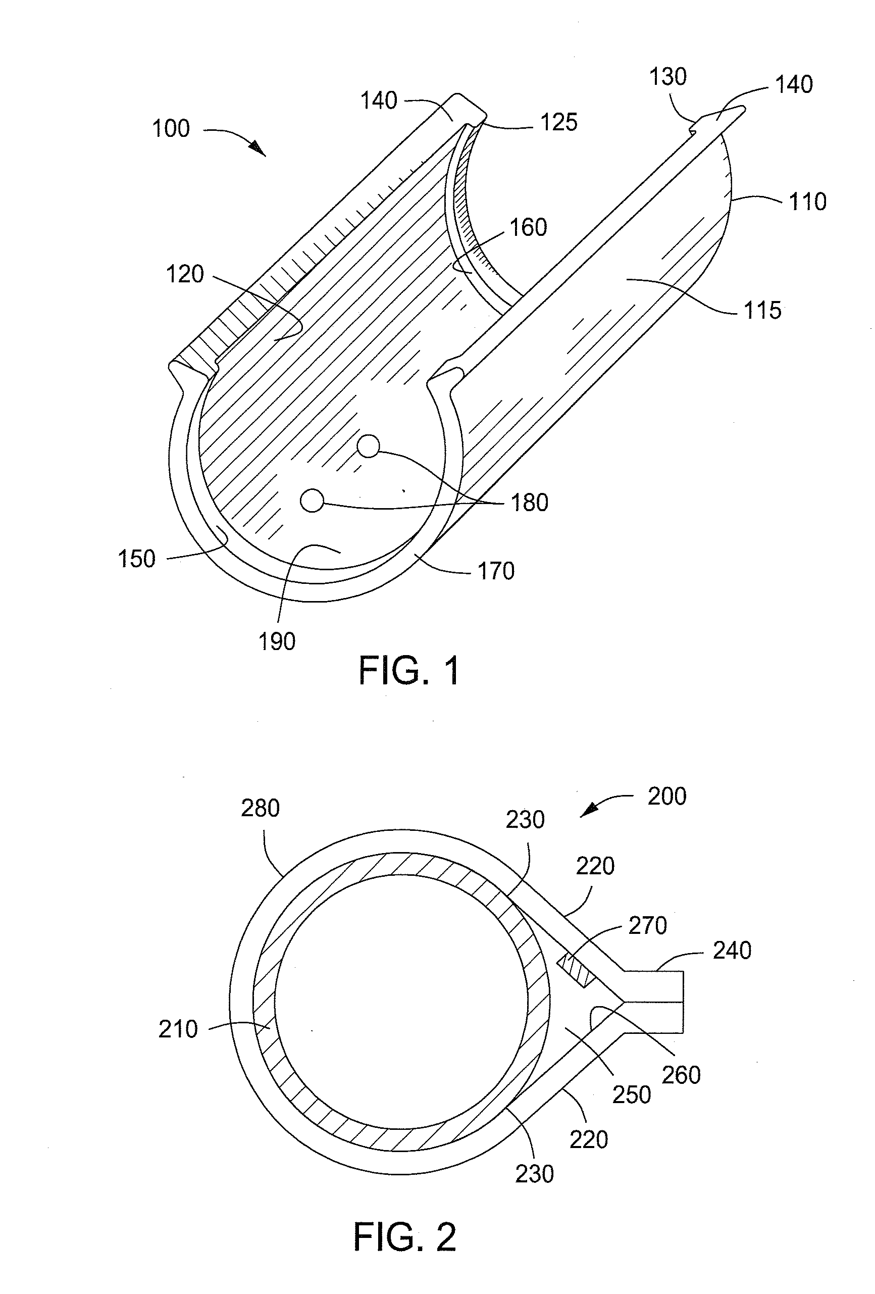
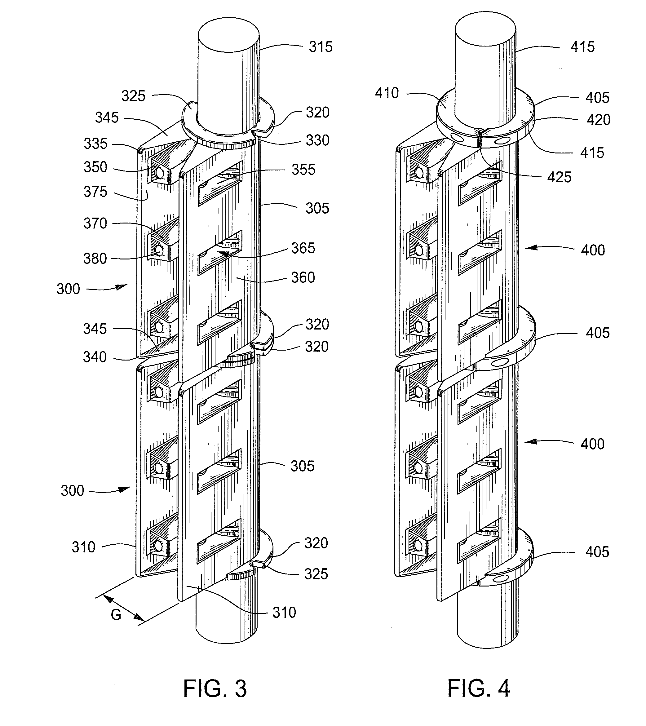
[0008]Systems and methods for reducing vortex-induced vibration and drag about a marine element are provided. In at least one specific embodiment, the system can include, but is not limited to, a shell rotatably mounted about the marine element, the shell having opposing edges defining a longitudinal gap configured to allow the shell to snap (be placed) around the marine element. A fin can be positioned along each opposing edge of the longitudinal gap wherein each fin can extend outwardly from the shell. The fins can be positioned on the shell so as to reduce vortex-induced vibration and minimize drag on the marine element. One or more antifouling agents can be disposed on, in, or about at least a portion of the shell, the fins, or a combination thereof.
[0009]In at least one specific embodiment, the method for reducing vortex-induced vibration and minimizing drag about a marine element can include disposing a vortex-induced vibration reduction device about a marine element. The vortex-induced vibration reduction device can include a rotatable shell. The rotatable shell can have opposing edges defining a longitudinal gap configured to allow the shell to snap around the marine element. A fin can be positioned along each opposing edge of the longitudinal gap, wherein each fin can extend outwardly from the shell. The fins can be positioned on the shell so as to reduce vortex-induced vibration and minimize drag on the marine element. One or more antifouling agents can be disposed on, in, or about at least a portion of the shell, the fin, or both.
[0010]In at least one specific embodiment, the method for reducing vortex-induced vibration and minimizing drag about a marine element can include disposing a vortex-induced vibration reduction device about a marine element. The vortex-induced vibration reduction device can include a U-shaped cylindrical shell with opposing edges defining a longitudinal gap. Parrallel fins can extend outwardly from the opposing edges of the shell. The parallel fins can be positioned so as to reduce vortex-induced vibration and minimize drag on the marine element. One or more antifouling agents can be disposed on, in, or about at least a portion of the shell, the fins, or both.

Problems solved by technology

When the frequency of the shedding vortices is at or near the natural frequency of the marine element, resonance occurs which can cause potentially destructive levels of vibration that adversely affect the platform structure itself, in addition to the equipment and personnel on the platform.
Biofouling is the undesirable accumulation of microorganisms, plants, algae, and other organisms on marine structures.
This build up of organisms on the surface of marine elements increases the weight and size of the VIV reduction devices, which in turn increases vortex-induced vibrations and drag forces exerted on the fairings.

Method used


Image

  • Marine Anti-foulant system and methods for using same
  • Marine Anti-foulant system and methods for using same
  • Marine Anti-foulant system and methods for using same

Examples


Embodiment Construction

[0018]A detailed description will now be provided. Each of the appended claims defines a separate invention, which for infringement purposes is recognized as including equivalents to the various elements or limitations specified in the claims. Depending on the context, all references below to the “invention” may in some cases refer to certain specific embodiments only. In other cases it will be recognized that references to the “invention” will refer to subject matter recited in one or more, but not necessarily all, of the claims. Each of the inventions will now be described in greater detail below, including specific embodiments, versions and examples, but the inventions are not limited to these embodiments, versions or examples, which are included to enable a person having ordinary skill in the art to make and use the inventions, when the information in this patent is combined with available information and technology.

[0019]Antifouling agents can reduce or prevent the growth of ma...


PUM

PropertyMeasurementUnit
Fractionaaaaaaaaaa
Temperatureaaaaaaaaaa
Flow rateaaaaaaaaaa

Abstract

Systems and methods for reducing vortex-induced vibration and drag about a marine element are provided. The system can include, but is not limited to, a shell rotatably mounted about the marine element, the shell having opposing edges defining a longitudinal gap configured to allow the shell to snap (be placed) around at least a portion of the marine element. A fin can be positioned along each opposing edge of the longitudinal gap, wherein each fin can extend outwardly from the shell. The fins can be positioned on the shell so as to reduce vortex-induced vibration and minimize drag on the marine element. One or more antifouling agents can be disposed on, in, or about at least a portion of the shell, the fins, or a combination thereof.

Description

BACKGROUND OF THE INVENTION[0001]1. Field of the Invention[0002]Embodiments of the present invention generally relate to systems and methods for protecting marine surfaces against biological fouling. More particularly, embodiments relate to systems and methods for reducing biological fouling on vortex-induced vibration reduction devices for offshore hydrocarbon exploration and production.[0003]2. Description of the Related Art[0004]In off-shore operations, vortex-induced vibration or “VTV” is caused by the flow of water around a tubular, such as a riser or other marine element. The flow of water leads to the shedding of vortices which cause alternating forces on either side of the marine element, thereby causing the element to vibrate. When the frequency of the shedding vortices is at or near the natural frequency of the marine element, resonance occurs which can cause potentially destructive levels of vibration that adversely affect the platform structure itself, in addition to the...

Claims


Application Information

Patent Timeline
IPC IPC(8): E02D5/60C09D7/63
CPCB63B21/663F16L1/123C09D5/1625C09D7/63F15D1/10
Inventor MASTERS, RODNEY H.GRIFFITH, BILLY L.
Owner ASSET INTEGRITY MANAGEMENT SOLUTIONS L L C D B A AIMS INT
Learn More