
Image Forming Device and Cleaning Device

a technology of cleaning device and forming device, which is applied in the direction of electrographic process apparatus, instruments, optics, etc., can solve the problems of poor easiness in handling, poor easiness in conveying, poor easiness in treating recovery mechanism, etc., to improve easiness in treatment, and improve easiness in conveying

Inactive Publication Date: 2009-07-23
SEIKO EPSON CORP
View PDF2 Cites 8 Cited by
  • Summary
  • Abstract
  • Description
  • Claims
  • Application Information

AI Technical Summary

Benefits of technology

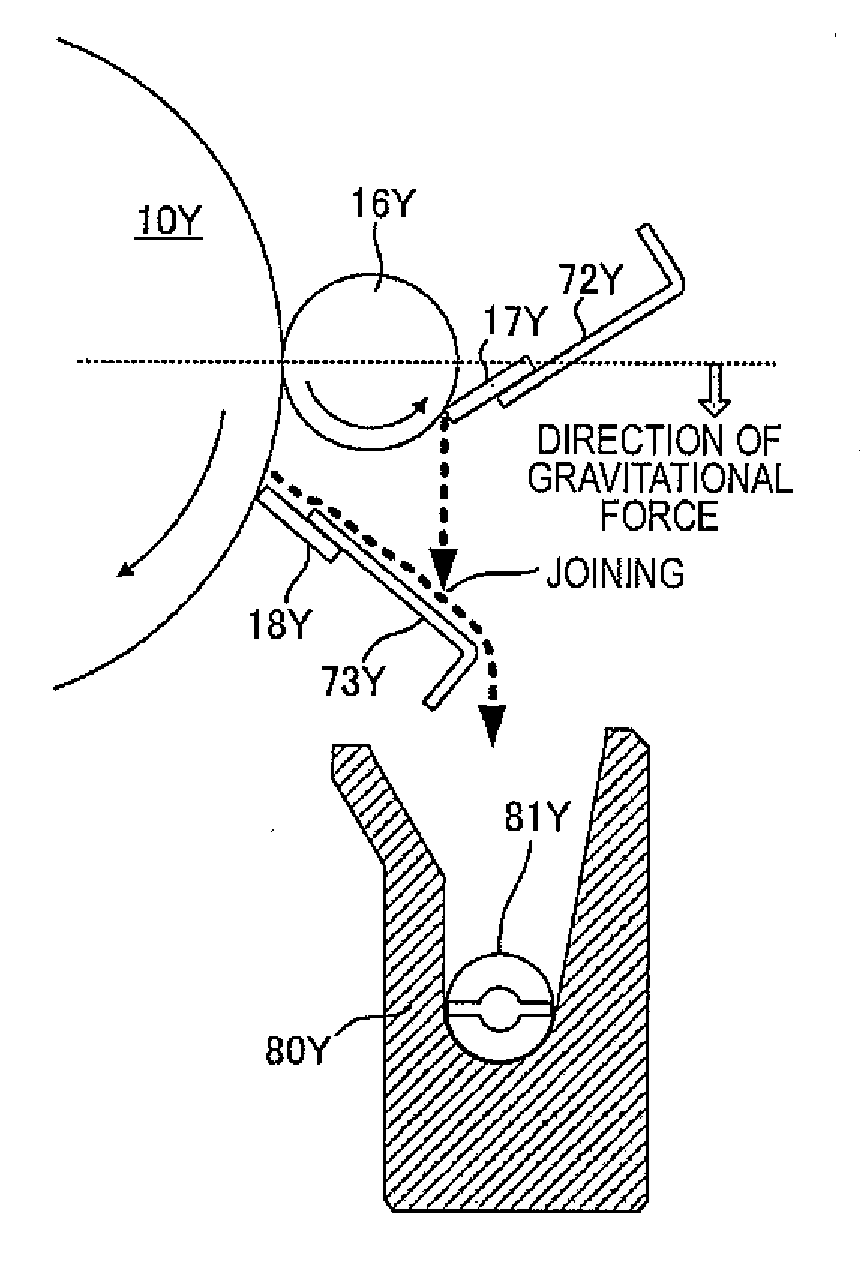
[0022]As described above, according to the aspects of the invention, it becomes possible to drop the liquid developer scraped off by the cleaning blade of the cleaning roller of the image carrier without running along the cleaning roller of the image carrier. Further, since the liquid developer scraped off by the cleaning blade of the cleaning roller of the image carrier is a liquid developer rich in the solid components, and has a lot of solid components, the easiness in conveying is poor. However, since the liquid developer scraped off by the image carrier cleaning blade, which is a liquid developer rich in the carrier component, is joined with the liquid developer scraped off by the cleaning blade of the cleaning roller of the image carrier to improve the easiness in conveying, and is guided to the image carrier recovery reservoir, there can be obtained an advantage of improving the easiness in treatment in the image carrier recovery reservoir.
[0039]Further, according to the referential aspects of the invention, the intermediate transfer member has elasticity, and therefore, it is difficult to press the blade for cleaning against the intermediate transfer member with high pressure. However, in the aspects of the present invention, since the intermediate transfer member is cleaned with the intermediate transfer member cleaning roller to which the bias voltage is applied, there is no possibility of damaging the intermediate transfer member with elasticity.

Problems solved by technology

However, in the case of removing the toner image on the image carrier or the intermediate transfer member having passed through the squeezing process, if the liquid developer is removed by separating the carrier liquid and the toner particles using the removing section for providing the electric field, since the removed liquid developer is rich in the solid components and contains a lot of solid components, the fluidity thereof is damaged to cause a problem that the easiness in conveying and the easiness in handling are poor, and the easiness in treating the recovery mechanism is poor.
Further, since the liquid developer scraped off by the cleaning blade of the cleaning roller of the image carrier is a liquid developer rich in the solid components, and has a lot of solid components, the easiness in conveying is poor.
Further, in the case in which the surface layer of the image carrier is made of amorphous silicon, the phenomenon that the toner particles remaining after the transfer process cause frictional electrification with a member having contact therewith such as the blade to damage the member is apt to occur.
Further, according to the aspects of the invention, the intermediate transfer member has elasticity, and therefore, it is difficult to press the blade for cleaning against the intermediate transfer member with high pressure.
Further, since the liquid developer scraped off by the cleaning blade of the cleaning roller of the image carrier is a liquid developer rich in the solid components, and has a lot of solid components, the easiness in conveying is poor.
Further, in the case in which the surface layer of the image carrier is made of amorphous silicon, the phenomenon that the toner particles remaining after the transfer process causes frictional electrification with a member having contact with each other such as the blade to damage the member is apt to occur.
Further, according to the referential aspects of the invention, the intermediate transfer member has elasticity, and therefore, it is difficult to press the blade for cleaning against the intermediate transfer member with high pressure.

Method used


Image

  • Image Forming Device and Cleaning Device
  • Image Forming Device and Cleaning Device
  • Image Forming Device and Cleaning Device

Examples


Embodiment Construction

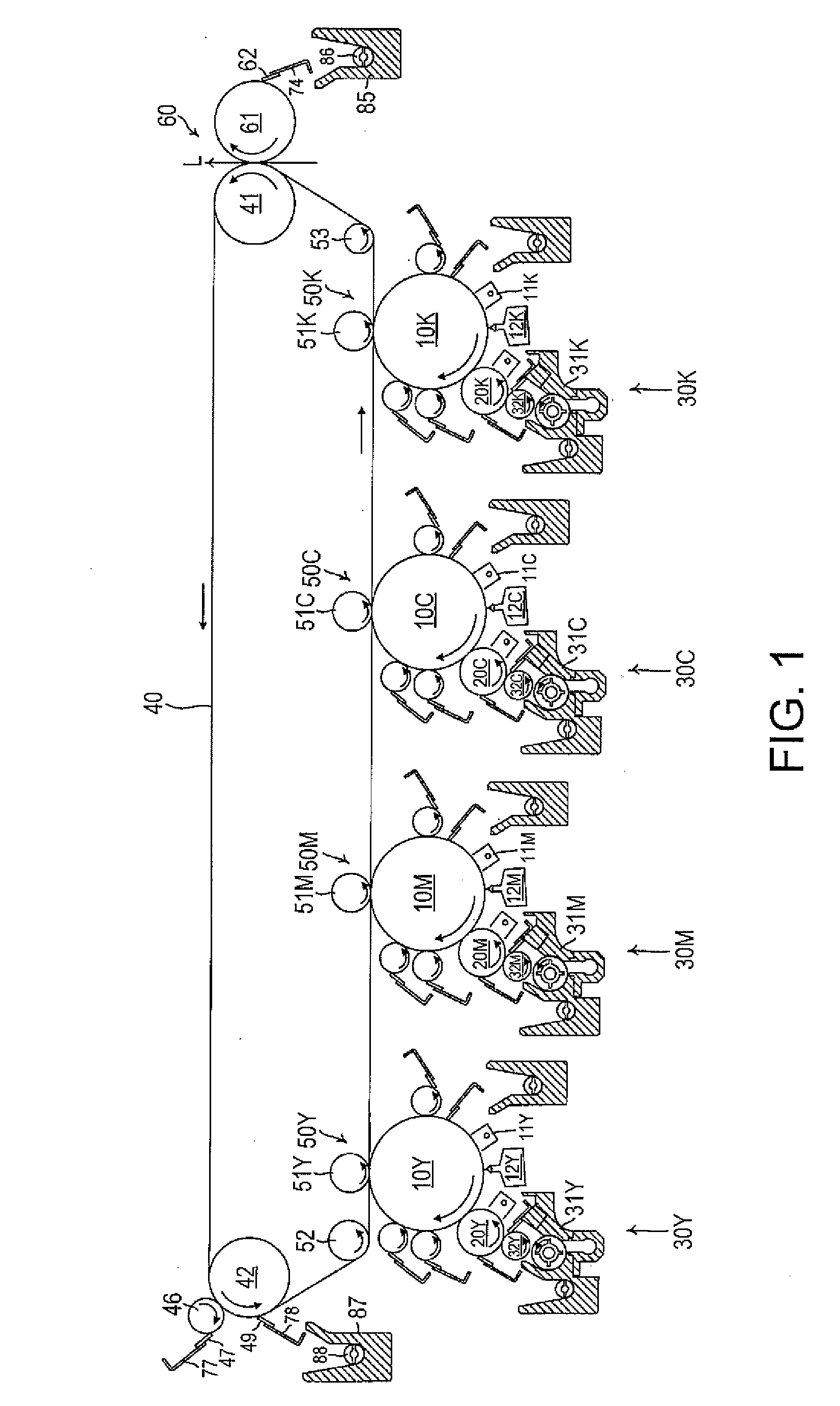
[0055]Some embodiments of the invention will hereinafter be explained with reference to the accompanying drawings. FIG. 1 is a diagram showing principal constituents forming the image forming device according to an embodiment of the invention. With respect to the image forming sections for respective colors disposed in the center area of the image forming device, development devices 30Y, 30M, 30C, and 30K are disposed in a lower area of the image forming device, and an intermediate transfer member 40 and a secondary transfer section (a secondary transfer unit) 60 are disposed in an upper area of the image forming device.

[0056]The image forming section is provided with image carriers 10Y, 10M, 10C, and 10K, corona chargers 11Y, 11M, 11C, and 11K, exposure units 12Y, 12M, 12C, and 12K (not shown), and so on. The exposure units 12Y, 12M, 12C, and 12K are each provided with a line head composed of LEDs or organic EL elements and an optical system, and the image carriers 10Y, 10M, 10C, a...


PUM


Abstract

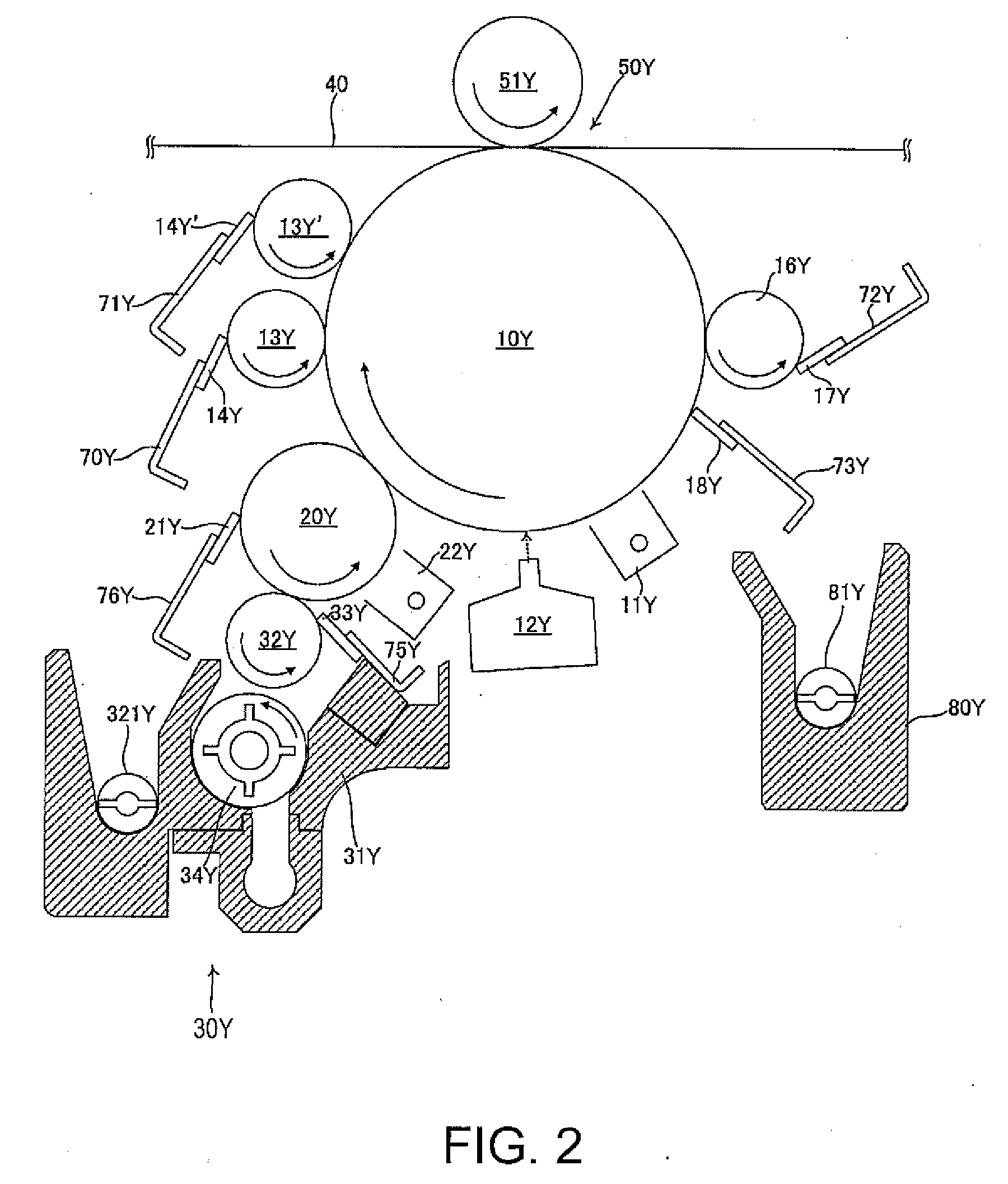
An image forming device includes a development section provided with a developer carrier adapted to perform development using a liquid developer including a carrier liquid and toner particles, an image carrier adapted to carry an image developed by the development section, an cleaning roller of the image carrier having contact with the image carrier, an cleaning blade of the cleaning roller of the image carrier having contact with the cleaning roller of the image carrier at one of a position on an imaginary line of an intersection between an imaginary plane passing through a center of a rotational axis of the cleaning roller of the image carrier and perpendicular to an imaginary vertical plane and a surface of the cleaning roller of the image carrier and a position lower than the imaginary line in a vertical direction, and an image carrier recovery reservoir adapted to store the liquid developer recovered by the cleaning blade of the cleaning roller of the image carrier.

Description

BACKGROUND[0001]1. Technical Field[0002]The present invention relates to a cleaning device adapted to clean an image carrier and an intermediate transfer member, the image carrier having a latent image formed on the surface thereof with a liquid developer composed of toner particles and a carrier, the latent image being developed, and the developed image being transferred to the intermediate transfer member. The invention also relates to an image forming device using such a cleaning device.[0003]2. Related Art[0004]There are proposed various types of wet image forming device developing a latent image using a high-viscosity liquid developer obtained by dispersing toner particles made of a solid component in a liquid solvent, thereby visualizing the electrostatic latent image. The developer used in such wet image forming devices has solid components (the toner particles) suspended in a high-viscosity organic solvent (a carrier liquid) with an electric insulation property made of silic...

Claims


Application Information

Patent Timeline
Patent Type & Authority Applications(United States)
IPC IPC(8): G03G21/00
CPCG03G15/104G03G21/105G03G21/0088
Inventor CHIBA, SATOSHIIKUMA, KEN
Owner SEIKO EPSON CORP
Learn More