
Massaging device

a technology of massaging device and power supply, which is applied in the field of power-driven massaging device, can solve the problems of massaging device dropping and damage, insufficient washing of hair and scalp, and insufficient protection of hair against friction

Inactive Publication Date: 2009-07-16
TWINBIRD CORP
View PDF4 Cites 28 Cited by
  • Summary
  • Abstract
  • Description
  • Claims
  • Application Information

AI Technical Summary

Benefits of technology

[0017]According to the present invention, the containing portion may operate correspondingly to deflection of the body plate.
[0005]Conventionally, as disclosed in Unexamined Japanese Patent Application Laid-open Publication No. 2007-229159, there is known a massaging device of the foregoing type that comprises a drive section and a treating section driven by the drive section. The drive section is provided with a frame that detachably holds the peripheral edge of a body plate of the treating section with a positional relationship relative to the drive section being fixed, and is further provided with a reciprocal drive mechanism that deflects the body plate in a direction intersecting with the surface of the body plate. The treating section comprises the body plate that is formed of a flexible material, and a plurality of protrusions protrudingly provided on the body plate. The massaging device causes the reciprocal drive mechanism to deflect the body plate of the treating section to repeatedly incline and raise the plurality of protrusions provided on the body plate in accordance with the deflection of the body plate, so that the plurality of protrusions open and close relative to one another, thereby massaging a scalp in various ways like kneading, rubbing, knocking, and the like by the opening / closing of the protrusions. As shown in FIGS. 6 and 7, the massaging device enables massaging of a scalp S by movement of plural kinds of protrusions 104, 105, and 106 in accordance with the deflection of a body plate 103 of a treating section 102 driven by a drive section 101 when the body plate 103, which is positioned in the treating section 102 driven by the drive section 101, repeats deformation between a downwardly deflected curved convex condition and an upwardly deflected curved concave condition, as if the protrusions 104, 105 and 106 function like fingers.

Problems solved by technology

Moreover, in whipping a shampoo, it is difficult to finely whip the shampoo by hands, resulting in insufficient washing of the hair and the scalp and insufficient protection for the hair against friction.
Further, if the massaging device is held by a slippery hand which has applied the shampoo to the hair, there is a possibility that the massaging device is dropped and damaged, and the user gets hurt in the worst occasion.
In this case, however, there is a possibility that the shampoo or the hair growth tonic runs down from the treating section and adheres to the drive section.
When the user holds the drive section to which the shampoo or the hair growth tonic adheres, the massaging device may be dropped and damaged, and the user may get hurt in the worst occasion.

Method used


Image

  • Massaging device
  • Massaging device
  • Massaging device

Examples


Embodiment Construction

[0030]Preferred embodiments of the present invention will be explained with reference to the accompanying drawings. The embodiments to be explained below shall not limit the scope of the present invention described in claims, and all of the structural components explained below shall not be always essential requirements to carry out the present invention.

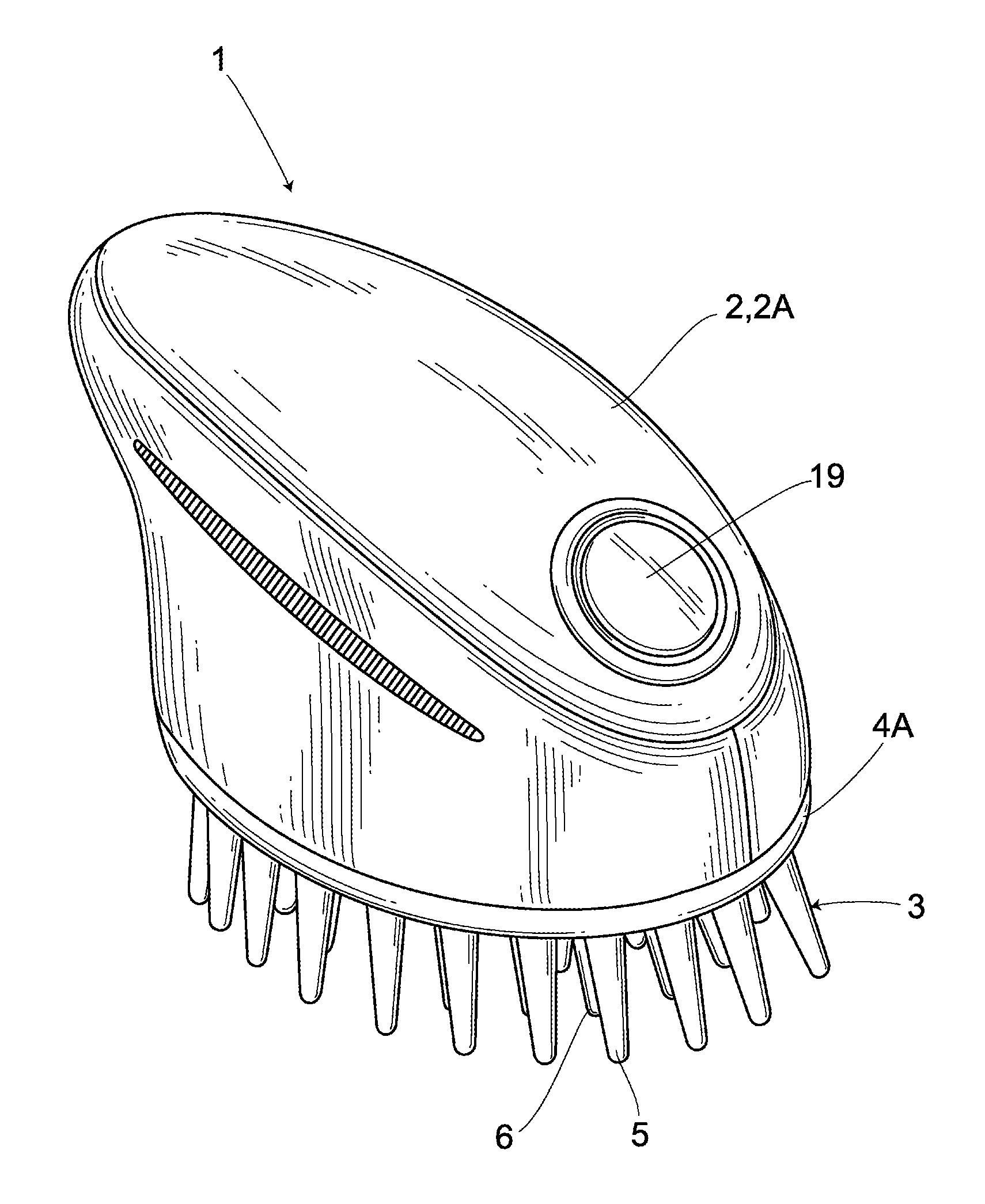
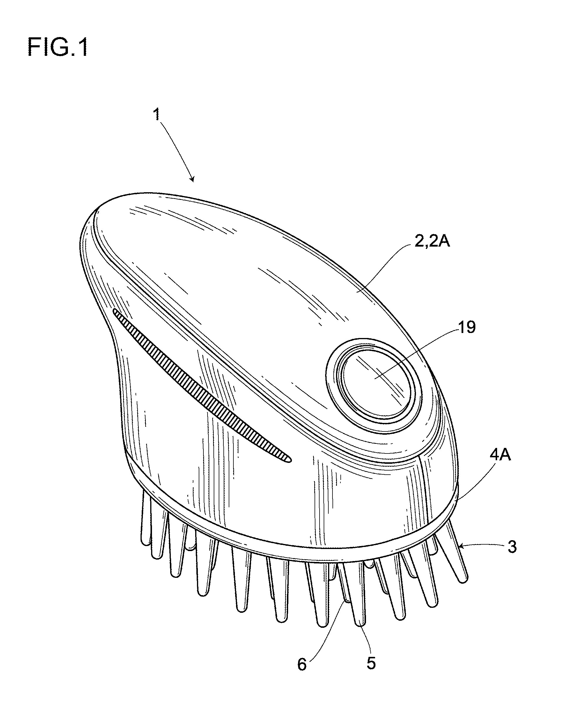
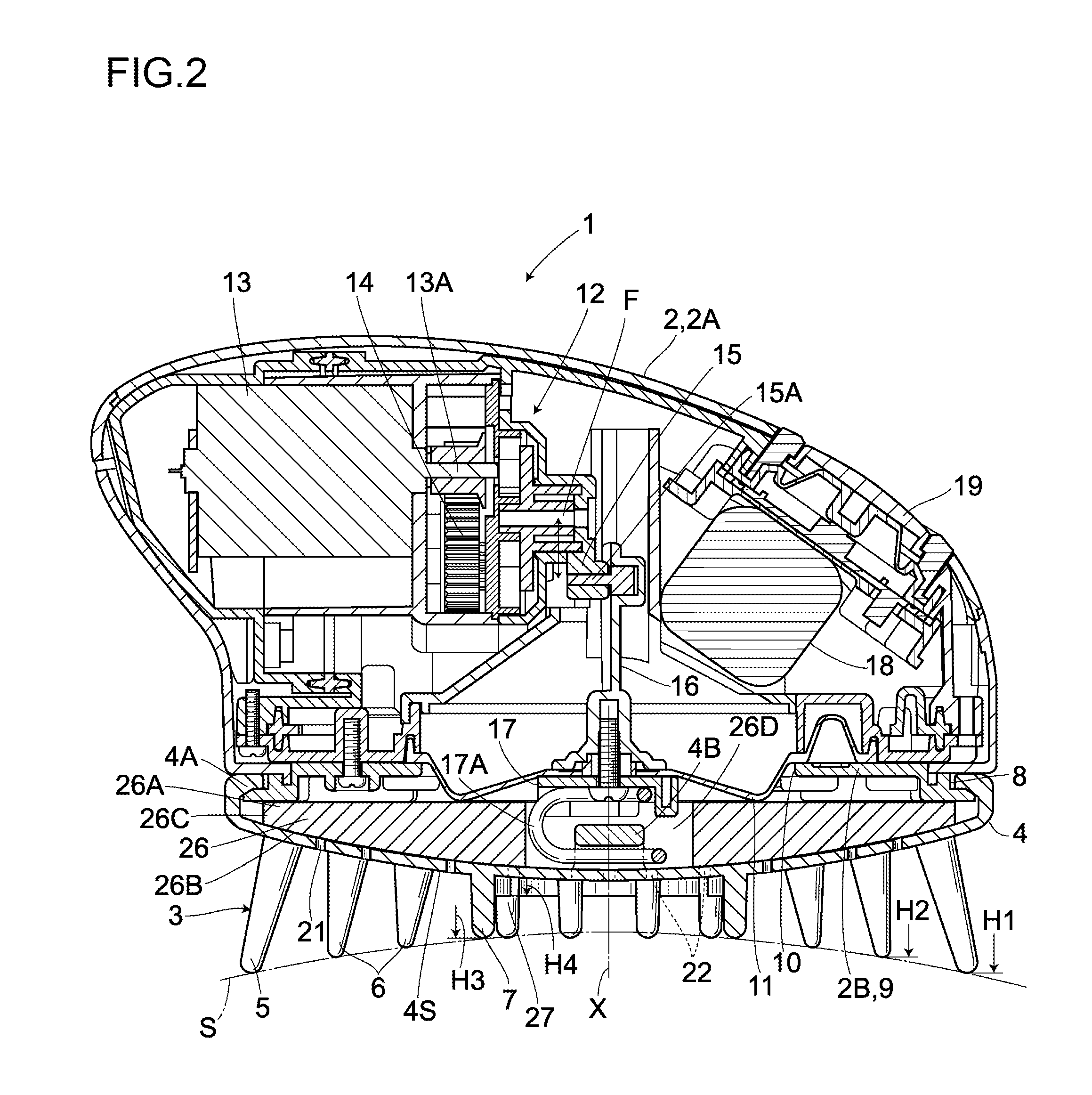
[0031]FIGS. 1 to 5 show the embodiment. In the embodiment, the vertical direction is defined with reference to a posture shown in FIG. 2. Reference numeral 1 denotes a massaging device of the present invention. The massaging device 1 comprises a massaging device main body 2 functioning as a drive section, and a treating section 3 detachably attached to the bottom part of the massaging device main body 2. The treating section 3 comprises a body plate 4 and three kinds of protrusions 5, 6 and 7 formed integral with the body plate 4 in a manner protruding in a downward direction which is a direction intersecting the bottom face of the ...


PUM


Abstract

In a massaging device, a treating section 3 has a body plate 4 formed of a flexible material and a plurality of protrusions intersecting the surface of the body plate and protruding downwardly. A massaging device main body has a reciprocal drive mechanism that deflects the body plate up and down. The small wall-like protrusions smaller than the third protrusions are provided on the surface of the body plate, and communicating portions communicating the interior with the exterior are provided inside the small wall-like protrusions. A containing portion for shampoo that is communicated with the communicating portions is provided between the massaging device main body and the body plate. A shampoo is applied inside the small wall-like protrusions with the surface of the body plate facing upwardly, and is supplied to the containing portion. The shampoo is whipped correspondingly to the deflection of the body plate while supplied from the communicating portions to perform hair washing and scalp massaging.

Description

CROSS-REFERENCE TO RELATED APPLICATION[0001]This application claims the benefit under 35 U.S.C § 119 of Japanese Patent Application No. 2008-007421, filed on Jan. 16, 2008, which is hereby incorporated by reference in its entirety.BACKGROUND OF THE INVENTION[0002]1. Field of the Invention[0003]The present invention relates to a power-driven massaging device, and more particularly, a massaging device which can be used for scalp massaging, kneading-style washing and the like in hair washing.[0004]2. Description of the Related Art[0005]Conventionally, as disclosed in Unexamined Japanese Patent Application Laid-open Publication No. 2007-229159, there is known a massaging device of the foregoing type that comprises a drive section and a treating section driven by the drive section. The drive section is provided with a frame that detachably holds the peripheral edge of a body plate of the treating section with a positional relationship relative to the drive section being fixed, and is fur...

Claims


Application Information

Patent Timeline
Patent Type & Authority Applications(United States)
IPC IPC(8): A61H7/00
CPCA61H2201/1463A61H2201/149A61H2201/1215A61H7/005A61H2201/105A61H2205/021
Inventor SAKAI, HIROEIKOBAYASHI, MASAHIROYOSHIDA, KATSUHIKO
Owner TWINBIRD CORP
Learn More