
Fitness treadmill

a treadmill and treadmill technology, applied in the field of fitness treadmills, can solve the problems of user inability to perform running exercise, difficult to achieve the effect of real exercise, and inability to exercise feet alternatively

Inactive Publication Date: 2009-07-16
SUPER MADE PRODS
View PDF27 Cites 32 Cited by
  • Summary
  • Abstract
  • Description
  • Claims
  • Application Information

AI Technical Summary

Benefits of technology

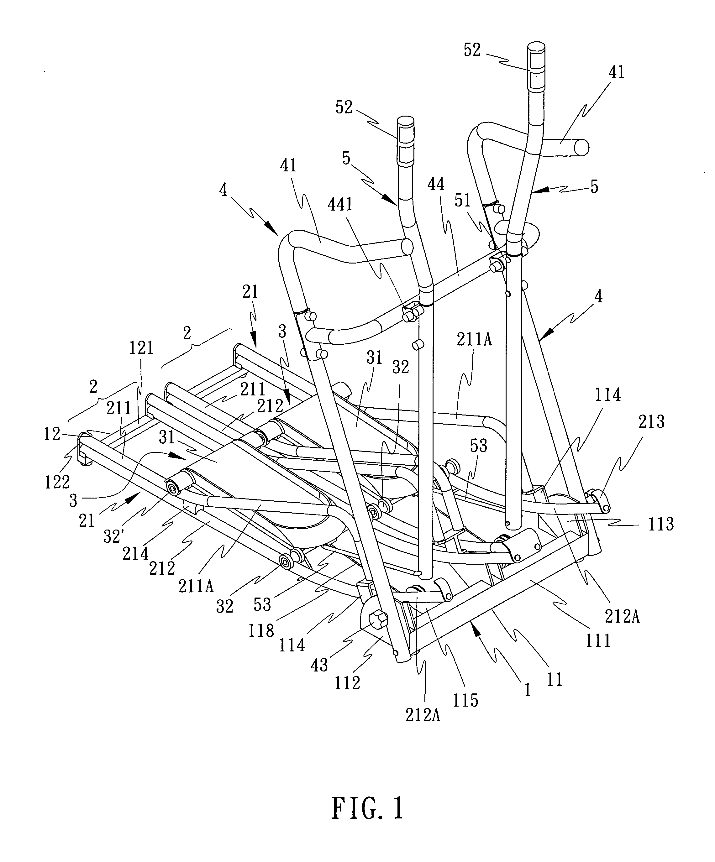
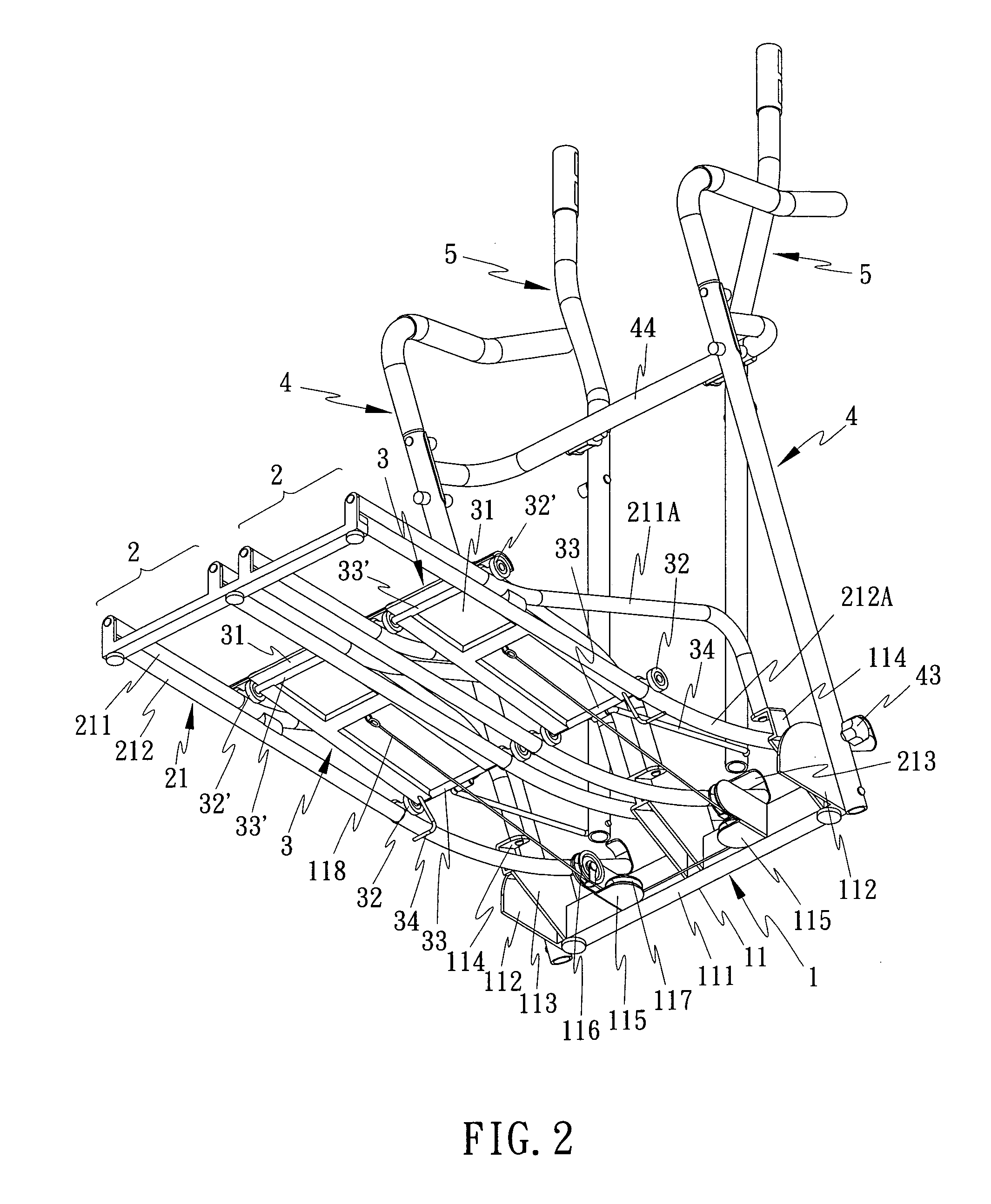
[0006]The purpose of the present invention is to provide a fitness treadmill that makes use the upper rail, lower rail, and stepping board assembled to the upper and lower rails design so as to allow stepping board perform to and fro rail with action similar to running in order to achieve the result of really exercising both feet as well as avoiding the sport injury of knee burden. And with the upper and lower rails design it is possible to alter the shape of the rails as desired to achieve different exercise result.
[0008]The other purpose of the present invention is to provide a fitness treadmill design that could install two rocking rods on the treadmill. The two said rocking rods are long rods that are pivoted at selected places on the lateral bar between the two handrails. A pulling strip is installed at the bottom of each rocking rod so that one end of the pulling strip is pivoted to the rocking rod and the other end is pivoted to the stepping board. In other words, the two rocking rods and the two stepping boards are jointly connected so that when the hands are holding the rocking rods the effect of swinging both arms while running can be achieved.

Problems solved by technology

The stepping boards are then connected to the cranks and hence could cause feet exercise alternatively.
Their common problem is in that user cannot perform running exercise, particularly the sing curved rail and the swinging exercise structures that can only allow user to swing the leg.
The muscles on the feet and legs could not exert force and therefore hard to achieve the effect of real exercise.
Whereas the treadmill installed with weight distribution wheel has complicated structure that is not only difficult to store away but also costs dearly.

Method used


Image

  • Fitness treadmill
  • Fitness treadmill
  • Fitness treadmill

Examples


Embodiment Construction

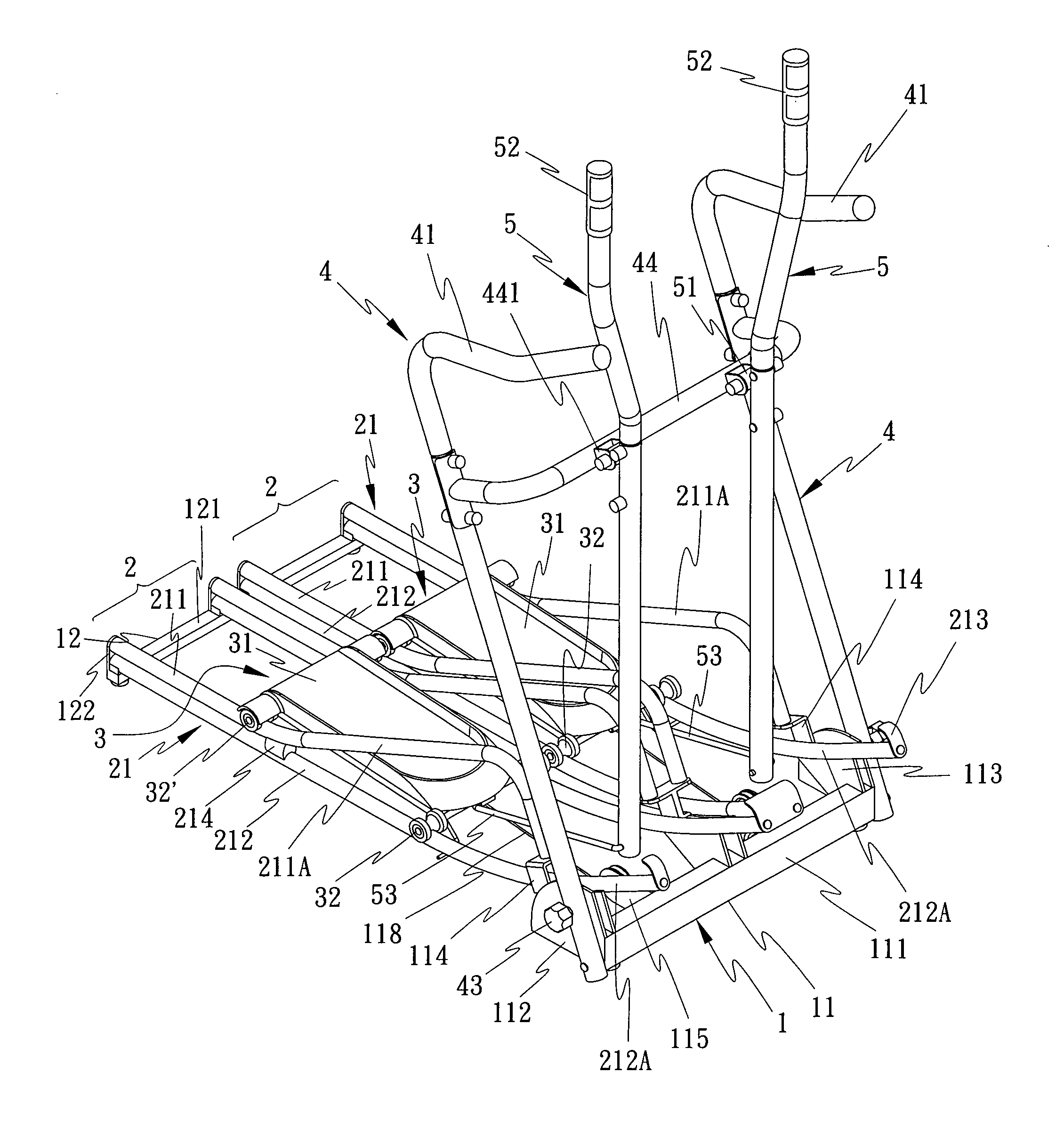
[0018]As shown in FIG. 1 and FIG. 2, the fitness treadmill of the present invention consists of a base 1, two sliding rail sets 2, and two stepping boards 3, and depending on the requirement of implementation two handrails 4 and two rocking rods 5 can be additionally installed, where

[0019]As shown in FIG. 1 and FIG. 2, the base 1 is for stabilizing the fitness treadmill and assembly of the sections described below comprising a front base 11 and a rear base 12. The said front base 11 consists of a lateral strip 111; each of the two sides is pivoted to a connecting board 112; inner side of the pivoted connecting board and the center of the lateral strip 111 is installed with a rail fixture 113; said rail fixture 113 can be in the form of a plate, each of the top ends can be installed with a U shape fixing part 114 that allows the upper rail 211 and the lower rail described above can be connected to the selected area of the fixing part 114. And behind the lateral strip 111 between each...


PUM


Abstract

A fitness treadmill consists mainly of a base, two sliding rail sets and two stepping boards; each of the rail set is formed by two rails in symmetrical shape; each rail has an upper rail strip assembled on the lower rail strip and the upper and lower rail strips are implemented with one or more than one guiding section based on the stepping board moving method; whereas the two stepping boards are respectively installed with front rollers and rear rollers on the two sides for each of the stepping board set to be assembled to each sliding rail set so that the rear rollers are pressed against the upper rail strip and the front rollers are pressed against the lower rail strip for the front and rear rollers to roll along the upper and lower rails and guiding section.

Description

BACKGROUND OF THE INVENTION[0001](a) Field of the Invention[0002]The present invention is related to a fitness treadmill, particularly a fitness treadmill structure design with special dual rail and stepping board structure.[0003](b) Description of the Prior Art[0004]The structural features of conventional treadmill is to install two pieces of movable stepping boards on the machine, allowing user to perform exercises similar to running and jogging while avoiding the vibration caused by impinge and resulting in burden to joints. However, there are several ways to drive the direction, height, or angle of the stepping boards. Some install weight distribution wheel at chosen place, and linking cranks are installed on both sides of the weight distribution wheel. The stepping boards are then connected to the cranks and hence could cause feet exercise alternatively. Others install a bobbing rod on both sides of the erecting pole of the machine. The stepping boards are respectively pivoted ...

Claims


Application Information

Patent Timeline
IPC IPC(8): A63B22/02
CPCA63B22/001A63B2210/50A63B2022/206A63B22/203
Inventor WU, SAN-CHING
Owner SUPER MADE PRODS
Learn More