Lever-type connector and a connector assembly

a technology of lever-type connectors and connector assemblies, which is applied in the direction of coupling device connections, coupling parts engagement/disengagement, electrical apparatus, etc., can solve the problems of positioning projections being deformed, positioning projections being crushed, and rubbing against the inner surface of levers, so as to reduce the degree of resilient deformation of resilient arms and facilitate deformation

Inactive Publication Date: 2009-07-16
SUMITOMO WIRING SYST LTD
View PDF7 Cites 11 Cited by
  • Summary
  • Abstract
  • Description
  • Claims
  • Application Information

AI Technical Summary

Benefits of technology

[0017]A resilient escaping portion preferably is cantilevered forward in an area between the escaping groove and the locking recess. Thus, the resilient escaping portion is deforme...

Problems solved by technology

However, the positioning projection abrades against the inner surface of the lever in the process of rotating the lever from the assembled position to the initial position.
Hence the p...

Method used


Image

  • Lever-type connector and a connector assembly
  • Lever-type connector and a connector assembly
  • Lever-type connector and a connector assembly

Examples


Embodiment Construction

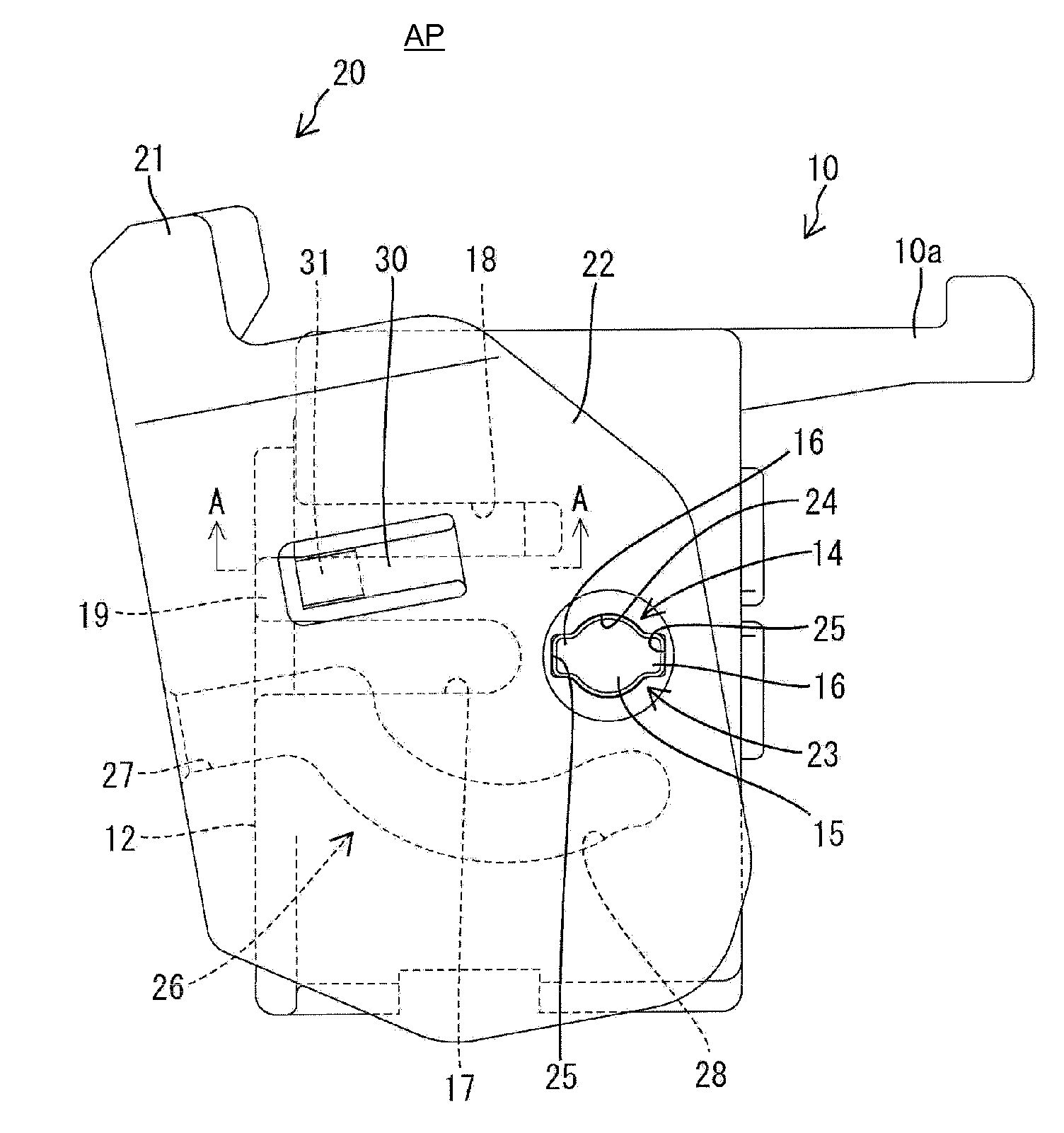
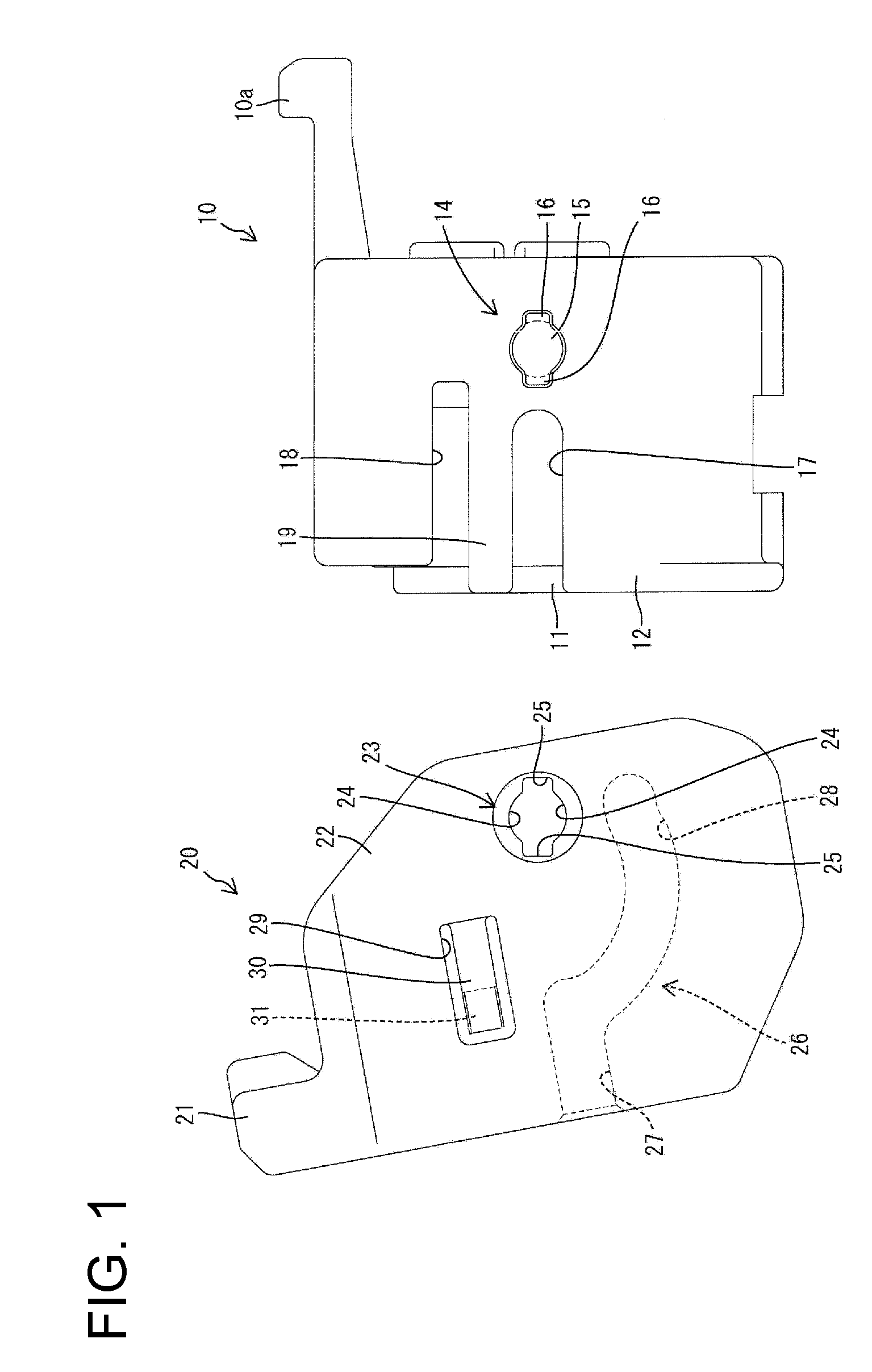
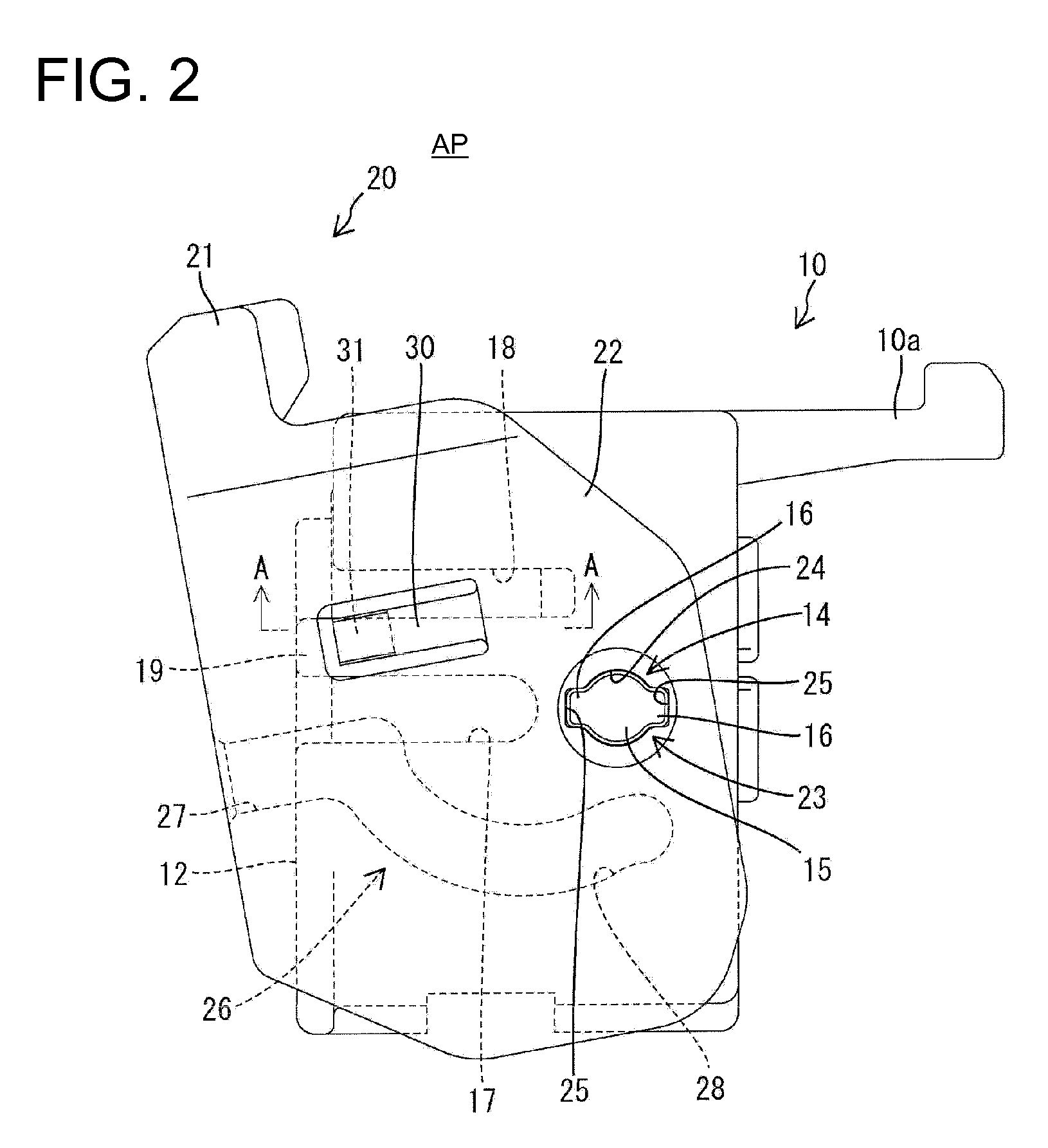
[0034]A lever-type connector assembly in accordance with the invention is illustrated in FIGS. 1 to 12. The connector assembly includes a first housing 10, a lever 20 mounted on the first housing 10 and a second housing 40 connectable with and separable from the first housing 10 along a connecting direction CD. Ends of the housings to be connected with each other are referred to herein as the front ends.

[0035]The first housing 10 is made unitarily e.g. of synthetic resin and has a substantially block-shaped terminal accommodating portion 11. Female terminal fittings (not shown) are accommodated in the terminal accommodating portion 11. A substantially tubular fitting 12 extends forward from a rear end of the terminal accommodating portion 11 and at least partly surrounds the terminal accommodating portion 11. A tubular connection space 13 is formed between the outer surface of the terminal accommodating portion 11 and the inner peripheral surface of the tubular fitting 12. The conne...


PUM


Abstract

Locking projections (31) formed on resiliently deformable resilient arms (30) hold a lever (20) at an initial position by engaging locking recesses (18). Resilient escaping portions (19), on which the locking projections (31) slide in the process of rotating the lever (20) between an assembled position and the initial position, are resiliently deformable in directions away from the locking projections (31). Upon rotating the lever (20) from the assembled position to the initial position after the lever (20) is assembled with a first housing (10), both the resilient arms (30) and the resilient escaping portions (19) are resiliently deformed. Thus, as compared with the case where only the resilient arms (30) are resiliently deformed, degrees of resilient deformation of the resilient arms (30) are reduced, wherefore deformations of the locking projections (31) to be crushed can be suppressed.

Description

BACKGROUND OF THE INVENTION[0001]1. Field of the Invention[0002]The invention relates to a lever-type connector and to a connector assembly.[0003]2. Description of the Related Art[0004]Japanese Unexamined Patent Publication No. H08-162209 discloses a lever-type connector with first and second housings that can be connected with one another. The first housing is formed with a supporting shaft and a lever is formed with a bearing hole mounted rotatably on the supporting shaft. The lever is formed with a cam groove and the second housing is formed with a cam follower that can engage in the cam groove. The first and second housing are fit lightly together with the lever at an initial position so that the cam follower enters the cam groove. The lever then is rotated to a connected position.[0005]A retaining projection is formed at the leading end of the supporting shaft and a cutout is formed in the inner circumference of the bearing hole. The retaining projection and the cutout are alig...

Claims


Application Information

Patent Timeline
IPC IPC(8): H01R13/631
CPCH01R13/62938
Inventor SHIBATA, TAKAHIRO
Owner SUMITOMO WIRING SYST LTD
Why Eureka
Try Eureka