
Shaft Rotating Device

a rotating device and shaft technology, applied in mechanical control devices, medical science, surgery, etc., can solve the problems of large frictional force required to fix the shaft, increased patient injury risk during the operation, and force to be overcome, so as to achieve the effect of convenient operation

Active Publication Date: 2009-07-09
UNIVERSITY OF DUNDEE
View PDF3 Cites 14 Cited by
  • Summary
  • Abstract
  • Description
  • Claims
  • Application Information

AI Technical Summary

Benefits of technology

The present invention provides a shaft rotating device and a medical instrument with the improved shaft rotating device. The shaft rotating device includes a frictional element and an operating element that are in driving connection with each other. The frictional element is in frictional contact with a counterpart surface to keep the shaft and handle stationary with respect to each other and movable against frictional forces. The operating element applies a torque to the shaft, which decreases the frictional forces and allows for easy rotation of the shaft with minimal physical effort. The shaft rotating device is advantageously easy to use, cost-effective, and provides variable frictional forces for easy rotation of the shaft.

Problems solved by technology

It is a disadvantage of the known shaft rotating device, that large frictional forces are required to fix the shaft rotationally stationary with respect to the handle during the operation.
For rotating the shaft relative to the handle, these frictional forces have to be overcome, which requires a large torque applied to the operating element during the shaft of the medical instrument being introduced into the body cavity.
This aggravates the handling of the instrument and increases the risk of injuries for the patient during the operation.
Furthermore, it is disadvantageous, that the strength of the torque applied to the operating element depends on the frictional forces between the surfaces of the shaft and the handle.
Moreover, the known shaft rotating device has the drawback, that rotating the shaft against the frictional forces requires a huge physical effort by the surgeon during the operation.
The operation is thus physically exhausting for the surgeon, which increases the possibility of unintentional malpractices of the surgeon.
A further disadvantage of the known shaft rotating device is, that any rotation of the shaft relative to the handle mechanically affects the surfaces of the involved components in terms of polishing them, so that these surfaces turn smooth.
As a result, the frictional forces between the shaft and the handle can decrease to an extent that the shaft can rotate in undesired fashion, when small external torques are applied to the shaft.

Method used


Image

  • Shaft Rotating Device
  • Shaft Rotating Device
  • Shaft Rotating Device

Examples


Embodiment Construction

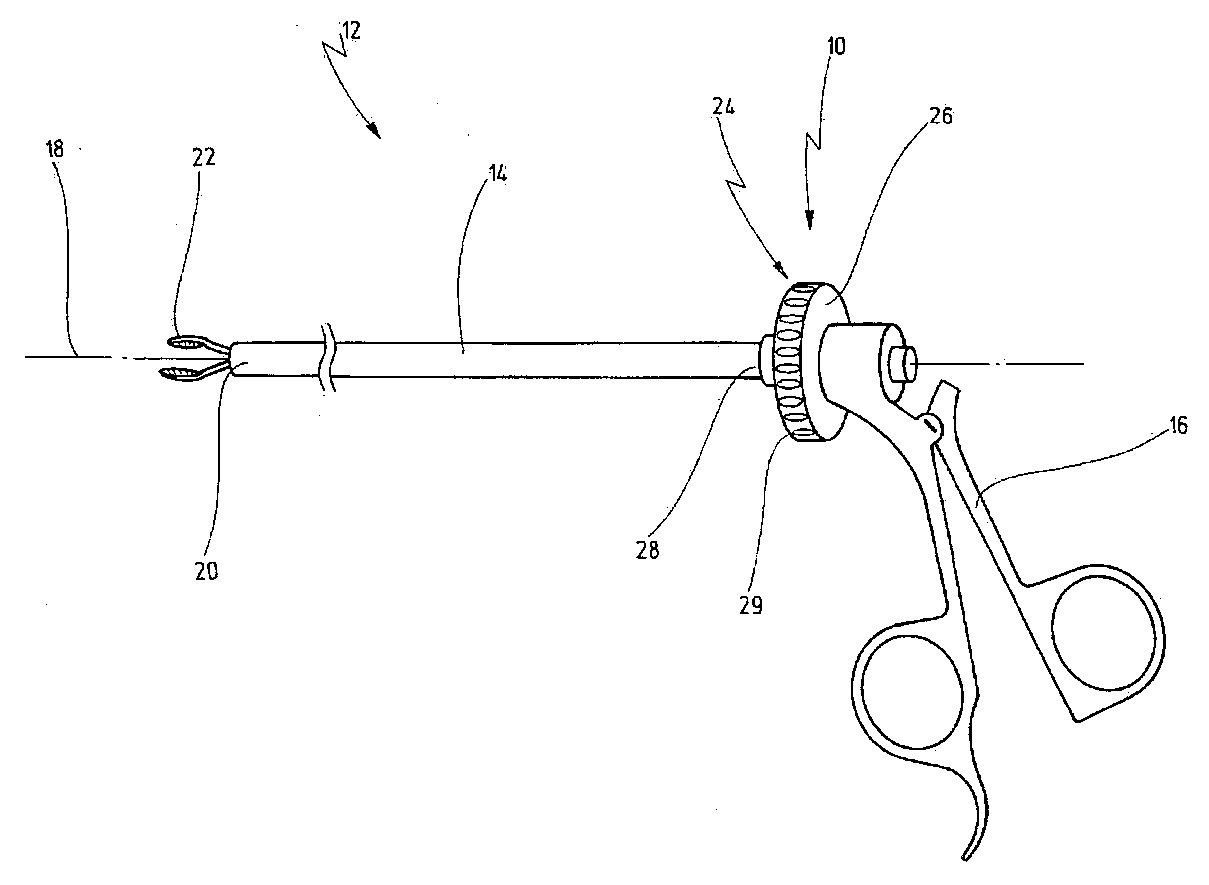
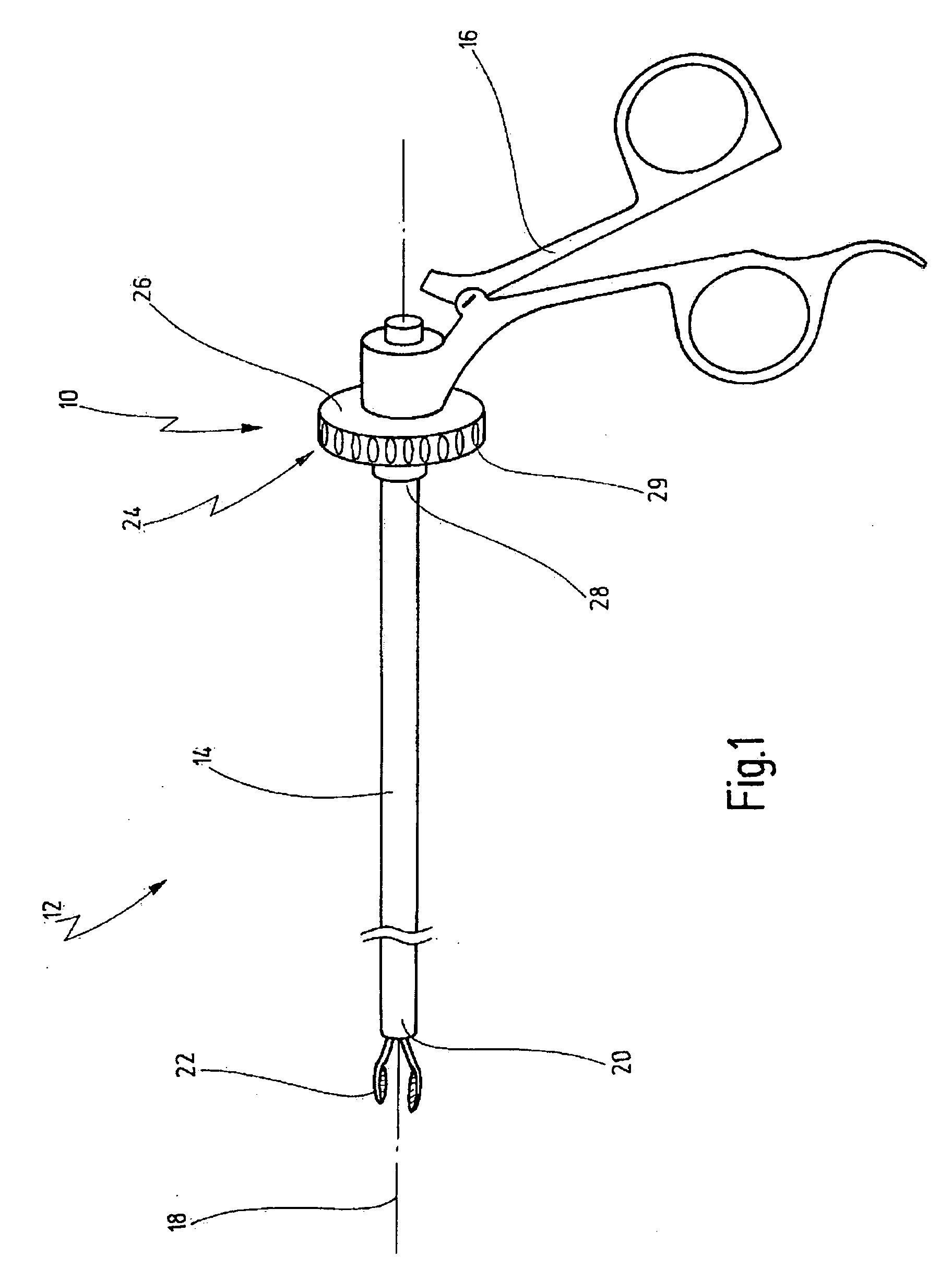
[0066]FIG. 1 shows, in a schematic representation, a shaft rotating device generally labelled with reference numeral 10 as part of a medical instrument 12. The shaft rotating device 10 is used for rotating an elongated hollow shaft 14 of the medical instrument 12 with respect to a handle 16 of the medical instrument 12 about a longitudinal axis 18 of the shaft 14. Further details of the shaft rotating device 10 are shown in FIGS. 2A through 5.

[0067]Preferably, the medical instrument 12 is made of steel to be easily cleaned after being used.

[0068]During an operation a distal portion 20 of the shaft 14 is introduced into a body cavity of a patient for e.g. grasping and / or cutting tissue e.g. of the appendix. Jaws 22, which are pivotably arranged at the distal portion 20 of the shaft 14, are connected with the handle 16 via an axially movable force transmission mechanism (not shown) such as a push / pull rod. Upon rotating the shaft 14 relative to the handle 16, the jaws 22 are rotated f...


PUM


Abstract

A shaft rotating device for rotating a shaft of a medical instrument about its longitudinal axis relative to a handle of the medical instrument comprises an operating element for rotating the shaft. The operating element is arranged at a proximal portion of the shaft and it is in driving connection with the shaft such that the shaft is rotatable relative to the handle against frictional forces. The shaft rotating device further comprises a frictional element with a surface. The surface of the frictional element is in frictional contact with the surface of a counterpart for keeping the shaft and the handle rotationally stationary with respect to each other and movable against the frictional forces. The operating element and the frictional element are in operational connection with respect to one another such that a torque applied to the operating element decreases the frictional forces. The shaft and the frictional element are in operational connection with one another such that a torque applied to a distal portion of the shaft increases the frictional forces.

Description

CROSS REFERENCE TO RELATED APPLICATION[0001]The present application claims priority of European patent application No. 08 000 033.4 filed on Jan. 3, 2008.BACKGROUND OF THE INVENTION[0002]The invention relates to a shaft rotating device for rotating a shaft of a medical instrument about its longitudinal axis relative to a handle of the medical instrument.[0003]The invention further relates to a medical instrument for endoscopic surgery, comprising a shaft and a handle, wherein the handle is arranged at a proximal portion of the shaft.[0004]A shaft rotating device is, for example, known from the firm catalogue of Karl Storz GmbH & Co., Tuttlingen, “Karl Storz—Endoskope, Laparoskopie”, 5. edition 1 / 2005, page SCC-INTRO 5B. This brochure shows a handle for the laparoscopy with the product number 33131 or 30131 which comprises the known shaft rotating device.[0005]The medical instrument comprising the known shaft rotating device is used for endoscopic operations in the field of the minim...

Claims


Application Information

Patent Timeline
Patent Type & Authority Applications(United States)
IPC IPC(8): A61B1/00G05G1/08
CPCA61B17/29A61B2017/2927Y10T74/20474A61B2017/347A61B2017/2929
Inventor FRANK, TIMOTHY GRAHAM
Owner UNIVERSITY OF DUNDEE
Learn More