
Driving Circuit and Method for Preventing Lamp from Blasting

a technology for driving circuits and lamps, applied in lighting devices, instruments, light sources, etc., can solve problems such as the inability to prevent lamps from blasting, and the possibility of lamps blasting, and achieve the effect of preventing lamp blasting and solving the problem of no solution

Inactive Publication Date: 2009-07-02
CORETRONIC
View PDF5 Cites 4 Cited by
  • Summary
  • Abstract
  • Description
  • Claims
  • Application Information

AI Technical Summary

Benefits of technology

[0004]The present invention is to provide a driving circuit for preventing a lamp from blasting caused by errors of a driving signal.
[0005]The present invention is to provide a method for preventing a lamp from blasting. The method includes detecting whether a control signal or a driving signal is essentially inconsistent with a standard control signal or a standard driving signal and stopping driving the lamps for preventing the lamp from blasting when the detected signal is essentially inconsistent with the standard signal.

Problems solved by technology

However, because the lamp may be rather delicate, if the driving signal has a great deviation in wave shape with respect to that of the standard driving signal, the lamp may blast.
So far, there is no solution to prevent the lamp from blasting although it is known that the deviation may lead the lamp to blast.

Method used


Image

  • Driving Circuit and Method for Preventing Lamp from Blasting
  • Driving Circuit and Method for Preventing Lamp from Blasting
  • Driving Circuit and Method for Preventing Lamp from Blasting

Examples


Embodiment Construction

[0021]It is to be understood that other embodiment may be utilized and structural changes may be made without departing from the scope of the present invention. Also, it is to be understood that the phraseology and terminology used herein are for the purpose of description and should not be regarded as limiting. The use of “including,”“comprising,” or “having” and variations thereof herein is meant to encompass the items listed thereafter and equivalents thereof as well as additional items. Unless limited otherwise, the terms “connected,”“coupled,” and “mounted,” and variations thereof herein are used broadly and encompass direct and indirect connections, couplings, and mountings.

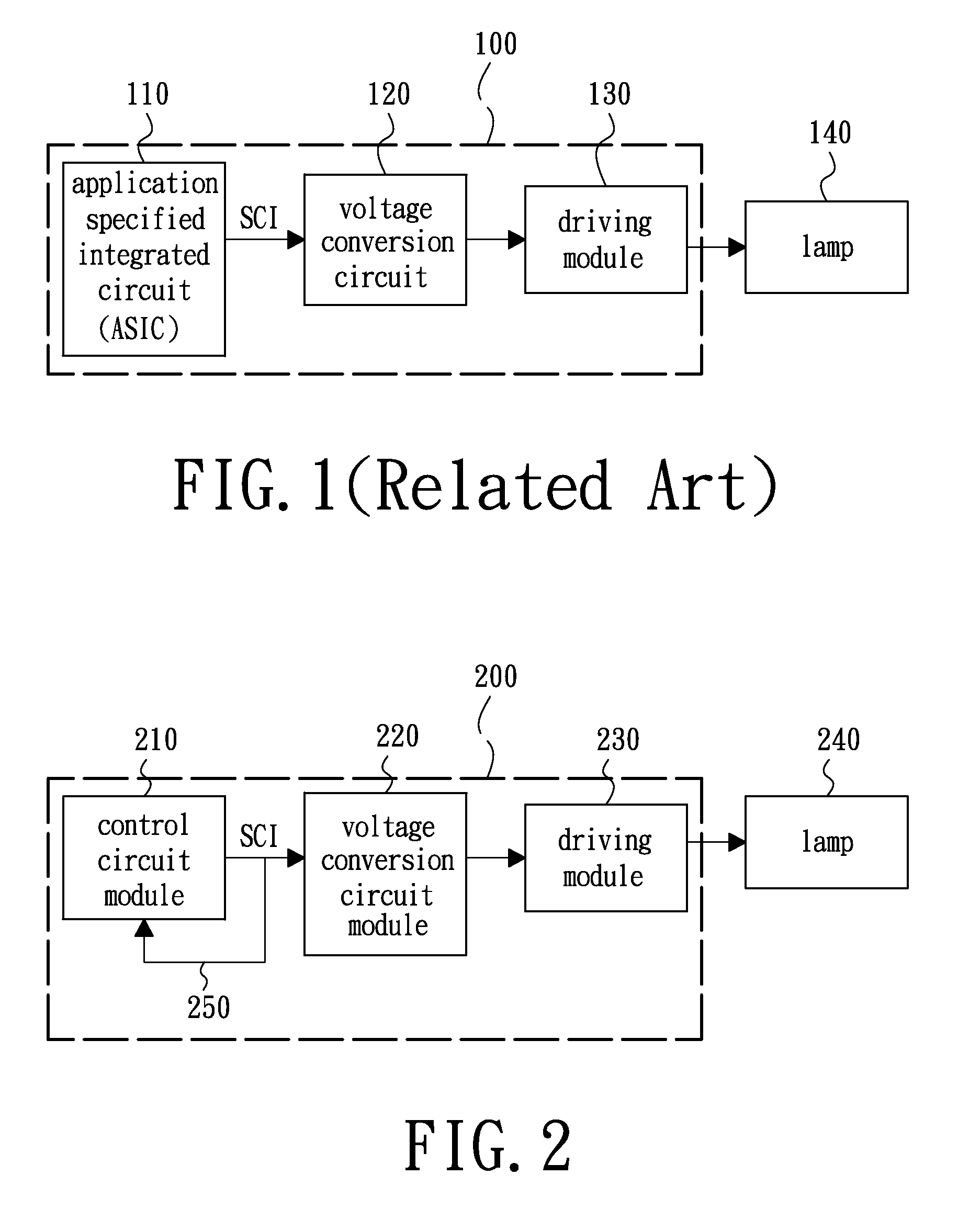
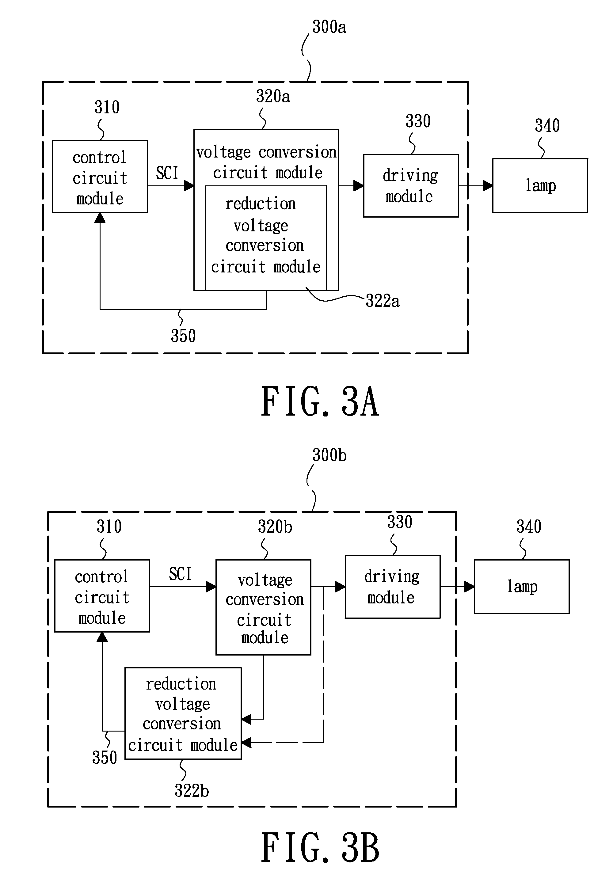
[0022]Referring to FIG. 2, a block diagram of a driving circuit capable of preventing a lamp from blasting according to an embodiment of the invention is provided. In this embodiment, the driving circuit 200 for driving a lamp 240 and capable of preventing the lamp 240 from blasting includes a control circu...


PUM


Abstract

In a driving circuit and method for preventing a lamp from blasting, a driving circuit includes a control circuit module, a voltage conversion circuit module, a driving module and a feedback circuit. The control circuit module outputs a first control signal according to a predetermined setting. The voltage conversion circuit module receives the first control signal and converts the first control signal into a second control signal. The driving module receives the second control signal and generates a driving signal according to the second control signal for driving the lamp. The feedback circuit electrically couples to one of the control circuit module, the voltage conversion circuit module and the driving module for receiving a feedback signal therefrom. The feedback signal is transmitted to the control circuit module, so that the control circuit module may adjust the first control signal according to the feedback signal.

Description

BACKGROUND[0001]The invention is related to a lamp driving circuit, especially to a driving circuit and a method for preventing lamps from blasting.[0002]As shown in FIG. 1, a conventional lamp used in a specific device such as a projector, because of the requirements on light emitting specified by the device, a lamp driving circuit 100 capable of providing a complicated driving signal is usually used to drive the lamp. In the lamp driving circuit 100, a control signal sync control input (SCI) is generated by an application specified integrated circuit (ASIC) 110. The control signal SCI is converted into a voltage level suitable for a driving module 130 to use via a voltage conversion circuit 120 and the voltage level is outputted to the driving module 130. The driving module 130 generates a driving signal for driving and controlling the lamp 140 to be turned on / off and adjusting the brightness of the lamp 140 according to a signal being received from the driving module 130.[0003]Fo...

Claims


Application Information

Patent Timeline
Patent Type & Authority Applications(United States)
IPC IPC(8): H05B37/02
CPCH05B41/285
Inventor WANG, CHIH-LINWU, PO-YEN
Owner CORETRONIC
Learn More