Cable winding mechanism with reduced friction

a winding mechanism and cable technology, applied in the field of cable winding mechanisms, can solve problems such as abraded components, and achieve the effects of reducing friction, reducing friction, and reducing the pulling force required to pull out the cabl

Inactive Publication Date: 2009-06-04
DELTA ELECTRONICS INC
View PDF10 Cites 11 Cited by
  • Summary
  • Abstract
  • Description
  • Claims
  • Application Information

AI Technical Summary

Benefits of technology

[0011]It is an object of the present invention to provide a cable winding mechanism for reducing the friction generated between the adjacent layers of the cable wound around the reel disc, between the reel disc and the case, and / or between the reel disc and the spool during the process of pulling or rewinding the cable. Due to the reduced friction, the pulling force required to pull out the cable is decreased and the problem of causing abrasion is minimized.

Problems solved by technology

Due to the friction, these components are abraded.

Method used


Image

  • Cable winding mechanism with reduced friction
  • Cable winding mechanism with reduced friction
  • Cable winding mechanism with reduced friction

Examples


Embodiment Construction

[0022]The present invention will now be described more specifically with reference to the following embodiments. It is to be noted that the following descriptions of preferred embodiments of this invention are presented herein for purpose of illustration and description only. It is not intended to be exhaustive or to be limited to the precise form disclosed.

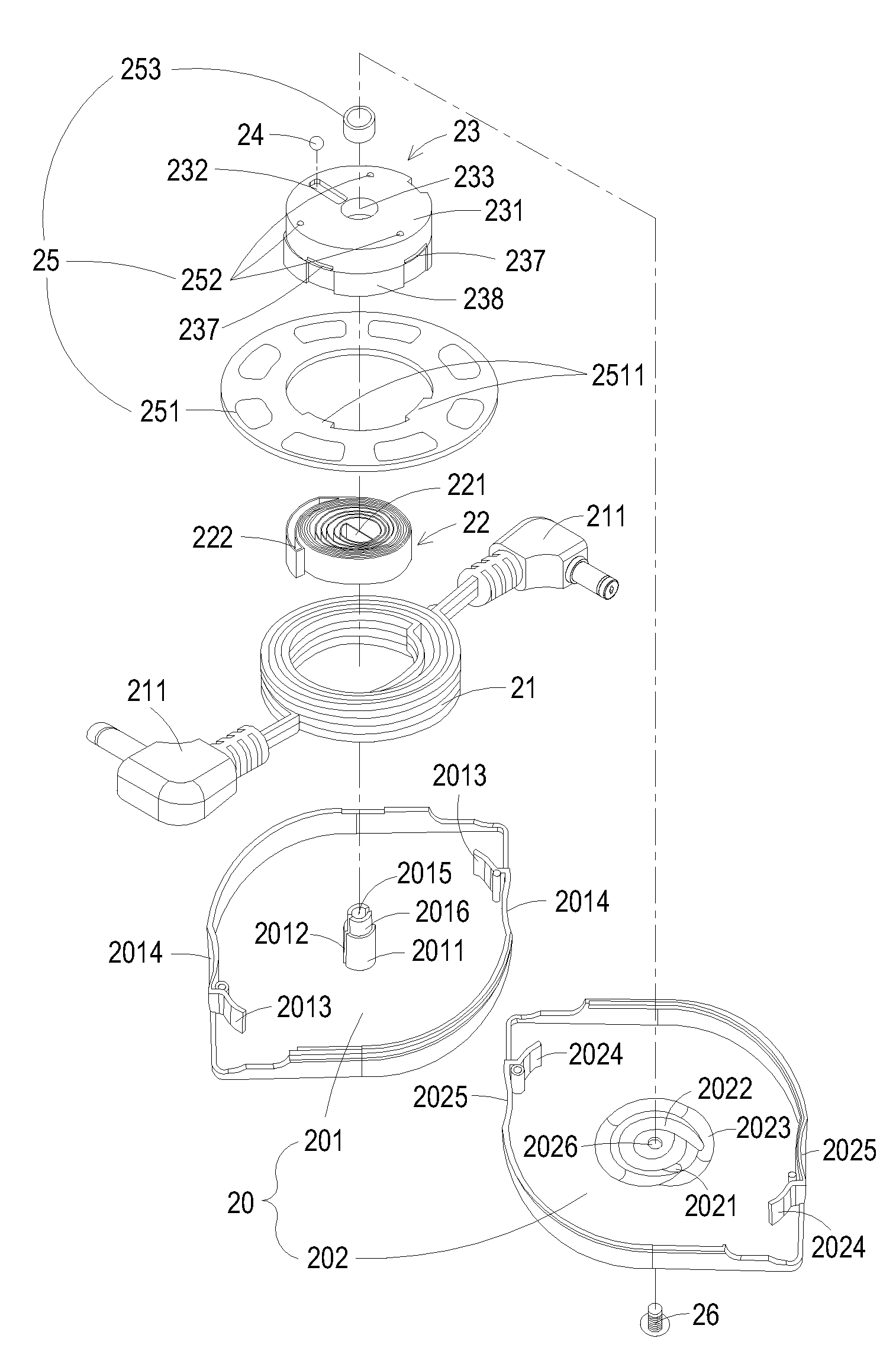
[0023]FIGS. 2A and 2B are respectively schematic assembled and exploded views illustrating a cable winding mechanism with reduced friction according to a preferred embodiment of the present invention. The cable winding mechanism 2 can be a power cable winding mechanism and principally includes a case 20, a cable 21, a spring device 22, a reel disc 23, a roller 24 and friction-reducing member 25.

[0024]An example of the cable 21 includes but is not limited to a DC power cable. The spring device 22 is for example a spiral spring. The cable 21 can be stored within the case 20. Both ends of the cable 21 have respective connectors 211,...


PUM


Abstract

A cable winding mechanism with reduced friction includes a cable, a case, a reel disc, a spring device, a roller and a friction-reducing member. The case includes a first case element and a second case element, wherein a cable locking structure is formed in an inner surface of the second case element. The reel disc has a confining groove. The roller is movable along the confining groove of the reel disc. When a pulling operation of the cable causes the roller to move in the cable locking structure of the second case element, a desired length of the cable is pulled out and locked. When the roller is detached from the cable locking structure, the cable pulled outside the case is rewound on the reel disc. The friction-reducing member is disposed on the reel disc for reducing friction during the process of pulling out or rewinding the cable.

Description

FIELD OF THE INVENTION[0001]The present invention relates to a cable winding mechanism, and more particularly to a cable winding mechanism with reduced friction.BACKGROUND OF THE INVENTION[0002]With increasing development of high technology industries, electronics devices such as notebook computers, phones, digital cameras and the like are widely used in our daily lives. Conventionally, these electronic devices are communicated with the power source via the linkage of power cables or communicated with other electronic devices via the linkage of signal cables. In other words, power cables and signal cables are utilized as transmission media for transmitting power and signals, respectively. Since these cables have several meters in length, it is critical to gather these cables for storage. Recently, many cable winding mechanisms have been proposed to wind cables for storage.[0003]For example, a USB cable adapter with a cable winding mechanism is disclosed in U.S. Pat. No. 6,733,328 an...

Claims


Application Information

Patent Timeline
Patent Type & Authority Applications(United States)
IPC IPC(8): B65H75/48
CPCB65H75/4434B65H2701/34B65H75/4449
Inventor WU, WEN-CHING
Owner DELTA ELECTRONICS INC
Why Eureka
Try Eureka