Animal House Ceiling Vent
a ceiling vent and animal house technology, applied in the field of attic or ceiling vents, can solve the problems of not providing for efficient flow and circulation of air within the animal house, and achieve the effect of efficient flow and circulation
- Summary
- Abstract
- Description
- Claims
- Application Information
AI Technical Summary
Benefits of technology
Problems solved by technology
Method used
Image

Examples
first embodiment
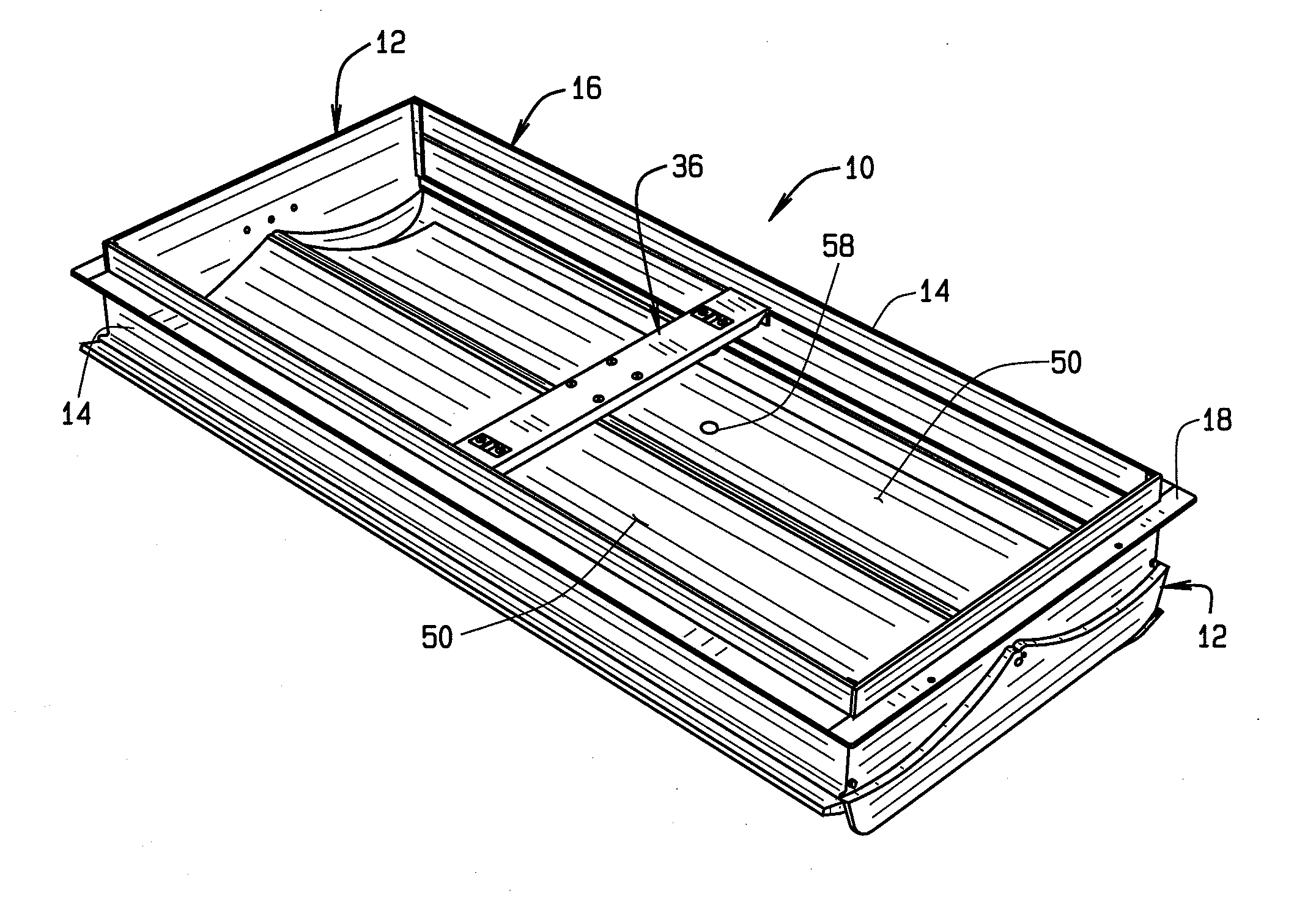
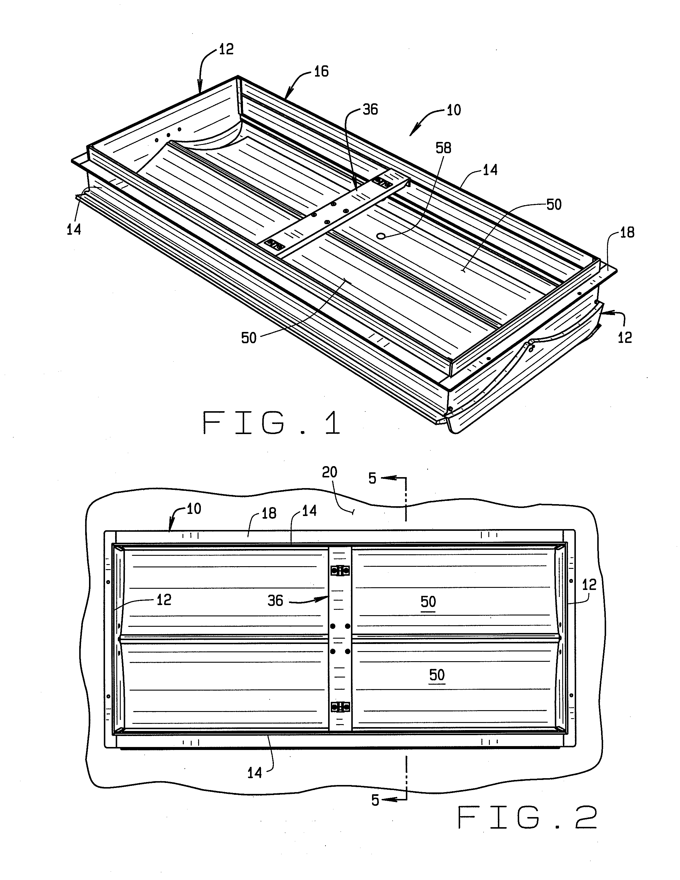
[0031]In a first embodiment, a pulley assembly 36 (shown best in FIGS. 5 and 6) extends across the frame 16 between the side panels 14, generally at the mid-point along the length of the vent assembly 10. The pulley assembly 36 includes a mounting bar 38 which is fixed to the side panels 14 in any desired manner, such as by gluing, welding, bolting, riveting, etc. A vertically oriented pulley 40 is spaced inwardly from each end of the mounting bar 38, with the pulleys 40 being suspended below the mounting bar 38. A pair of horizontally oriented pulleys 42 is spaced outwardly from the approximate center of the mounting bar, such that each horizontal pulley 42 is generally aligned with one of the openings 26 in the end panel 12. The horizontal pulleys 42 are contained within a pulley housing or bracket 44 which suspends the horizontal pulleys 42 beneath the mounting bar 38. The horizontal pulleys 42 and vertical pulleys 40 are all spaced below the mounting bar 38 by approximately the ...
second embodiment
[0042]the attic vent is shown in FIGS. 11-15. The vent assembly 110 is substantially similar to the vent assembly 10. However, the main components of the vent assembly 110 are made from metal as opposed to plastic. The vent assembly 110 comprises a pair of opposed end panels 112 and a pair of opposed side panels 114 which, in combination, define a frame 116 which is open at its top and bottom. A flange 118 extends around the frame 116 and is spaced slightly below the top edge of the end and side panels 112 and 114. As will be described below, the portion of the flange 118 extending along the side panels 114 is integral with the side panels, and the portion of the flange extending along the end panels 112 is comprised of a separate strip of metal which is secured at its opposite ends to the side panel flange segments.
[0043]The end panels 112 are identical. Each end panel 112 includes generally flat inner and outer surfaces. As seen, the end panel 112 is divided into a lower potion 11...
third embodiment
[0049]the ceiling vent assembly is shown in FIGS. 16A-16C. The ceiling vent assembly 210 is substantially similar to the vent assemblies 10 and 110, and the main components may be made from either metal or plastic. The vent assembly 210 comprises a pair of opposed end panels 212 and a pair of opposed side panels 214 which, in combination, define a frame 216 which is open at its top and bottom. A flange 218 extends around the frame 216 and is spaced slightly below the top edge of the end and side panels 212 and 214. As will be described below, the portion of the flange 218 extending along the side panels 214 is integral with the side panels, and the portion of the flange extending along the end panels 212 is comprised of a separate strip of metal which is secured at its opposite ends to the side panel flange segments.
[0050]The end panels 212 are identical. Each end panel 212 includes generally flat inner and outer surfaces. As seen, the end panel 212 is divided into a lower potion 21...
PUM
 Abstract
Description
Claims
Application Information
 - R&D
- Intellectual Property
- Life Sciences
- Materials
- Tech Scout
- Unparalleled Data Quality
- Higher Quality Content
- 60% Fewer Hallucinations
Browse by: Latest US Patents, China's latest patents, Technical Efficacy Thesaurus, Application Domain, Technology Topic, Popular Technical Reports.
© 2025 PatSnap. All rights reserved.Legal|Privacy policy|Modern Slavery Act Transparency Statement|Sitemap|About US| Contact US: help@patsnap.com