
Integrated bidirectional coupler

Active Publication Date: 2009-05-21
STMICROELECTRONICS (TOURS) SAS
View PDF8 Cites 40 Cited by
  • Summary
  • Abstract
  • Description
  • Claims
  • Application Information

AI Technical Summary

Benefits of technology

[0014]It would also be desirable to improve the reliability of the measurements by the coupler on the ports of its secondary line.
[0016]At least one embodiment enables significantly decreasing the coupler bulk.

Problems solved by technology

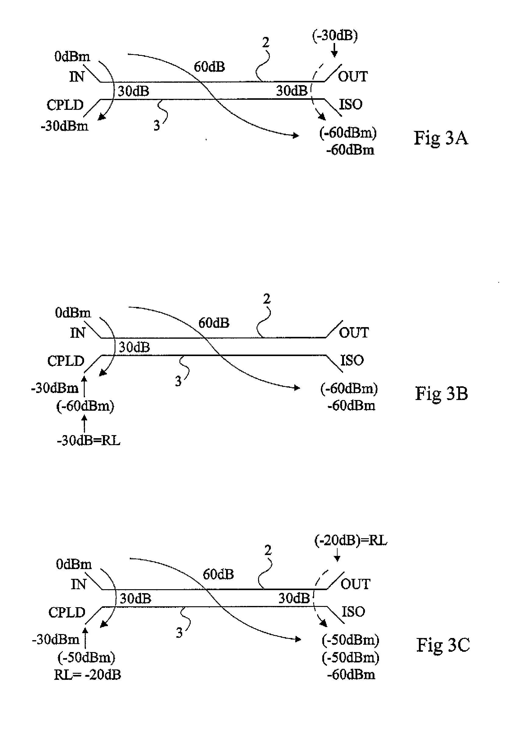
Such a perfect matching is difficult to obtain in practice.
In particular, the port from which the power portion is sampled by coupling is seldom ideally matched.
As a result, parasitic reflections generate errors on the recovered information.
Most often, the coupler is placed on an insulating substrate (for example, of printed circuit type) to be associated with other circuits It is then not possible to ensure a perfect matching (typically, at 50 ohms) of the measurement port.
However, at constant coupling factor, this requires increasing the coupling, and thus the coupler size, and thus increases transmission losses.
Further, this only postpones the problem of parasitic reflections, which then appear for higher levels of mismatch of the secondary line ports.

Method used


Image

  • Integrated bidirectional coupler
  • Integrated bidirectional coupler
  • Integrated bidirectional coupler

Examples


Embodiment Construction

[0038]The same elements have been designated with the same reference numerals in the different drawings. Further, for clarity, only those elements which are useful to the understanding of the present invention have been shown and will be described. In particular, the different possible exploitations of the signal sampled from the secondary line of the coupler have not been detailed, the present invention being compatible with any current use.

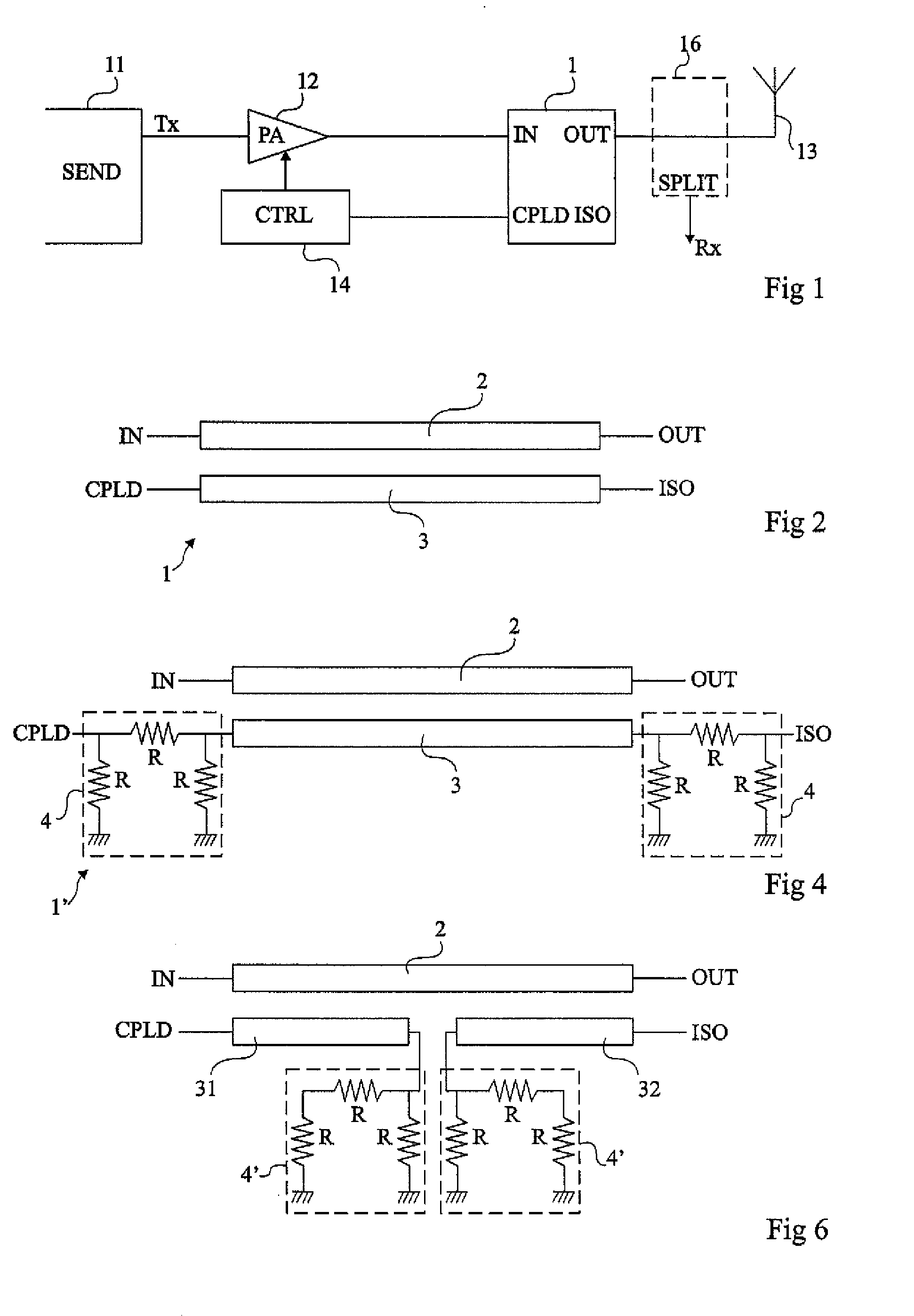
[0039]FIG. 1 is a block diagram of a radio-frequency transmission line using a coupler 1 of the type to which the present invention applies as an example.

[0040]A transmit circuit 11 (SEND) sends a signal Tx to be transmitted to an amplifier 12 (PA) having its output intended to be connected to an antenna 13. A main line of a coupler 1 is interposed between the output of amplifier 12 and antenna 13. A so-called access port IN is on the side of amplifier 12 while a so-called access port OUT (sometimes also designated as DIR) is on the antenna side...


PUM


Abstract

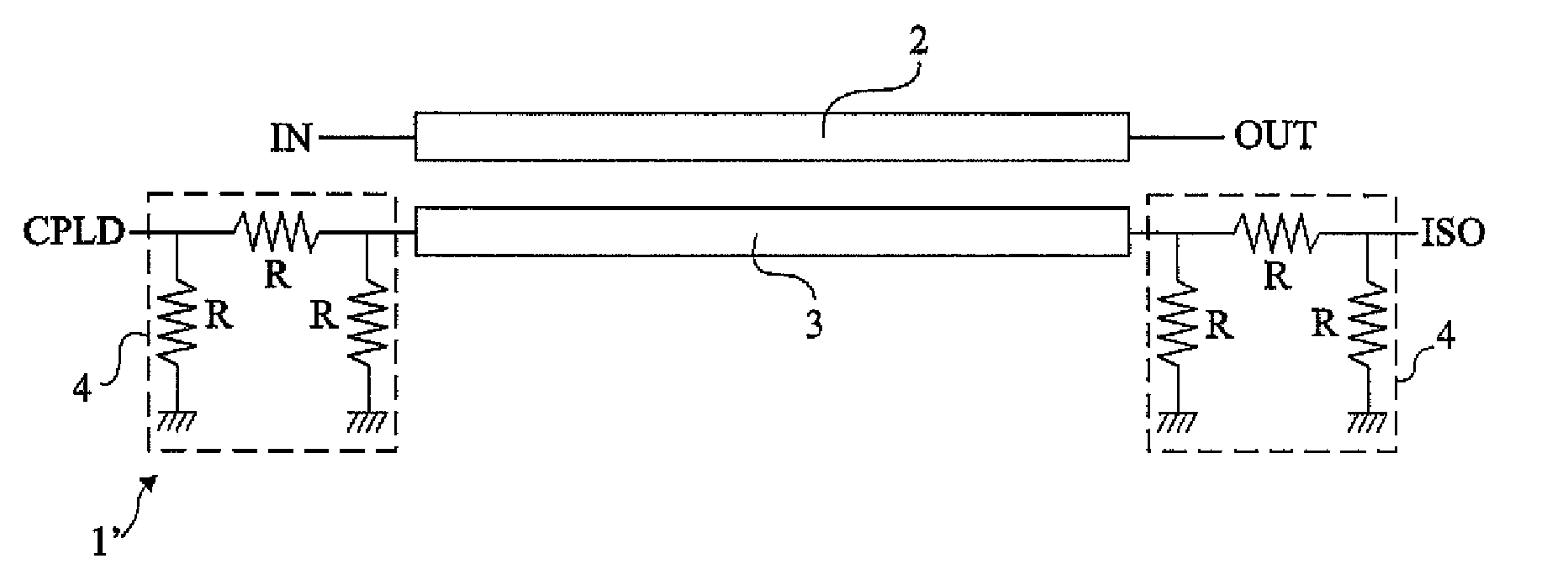
A distributed-line directional coupler including: a first conductive line between first and second ports intended to convey a signal to be transmitted; and a second conductive line, coupled to the first one, between third and fourth ports, the second line being interrupted approximately at its middle, the two intermediary ends being connected to attenuators.

Description

CROSS REFERENCE TO RELATED APPLICATIONS[0001]This application claims the priority benefit of French patent application number 07 / 59185, filed on Nov. 20, 2007, entitled “Integrated Bidirectional Coupler,” which is hereby incorporated by reference to the maximum extent allowable by law.BACKGROUND OF THE INVENTION[0002]1. Field of the Invention[0003]The present invention generally relates to the electronic industry and, more specifically, to radio-frequency transceiver systems. The present invention more specifically relates to a bi-directional coupler and to its applications.[0004]2. Discussion of the Related Art[0005]A coupler is generally used to draw part of the power present on a so-called main or primary transmission line towards another so-called coupled or secondary line located in the vicinity.[0006]Couplers are distributed in two categories according to whether they are formed of discrete passive components (it is then spoken of couplers with local elements) or of conductive...

Claims


Application Information

Patent Timeline
IPC IPC(8): H01P5/18
CPCH01P5/18H01P5/184
Inventor DUPONT, FRANCOISEZZEDDINE, HILALCHARLEY, SYLVAIN
Owner STMICROELECTRONICS (TOURS) SAS
Learn More