
Buoy holder for fish culling

a technology for fish culling and buoys, which is applied in the direction of rigid containers, fishing, transportation and packaging, etc., can solve the problems of inability to clip the opposite end of the buoy, and small siz

Inactive Publication Date: 2009-04-30
MULLINS JEFFERY L
View PDF70 Cites 6 Cited by
  • Summary
  • Abstract
  • Description
  • Claims
  • Application Information

AI Technical Summary

Benefits of technology

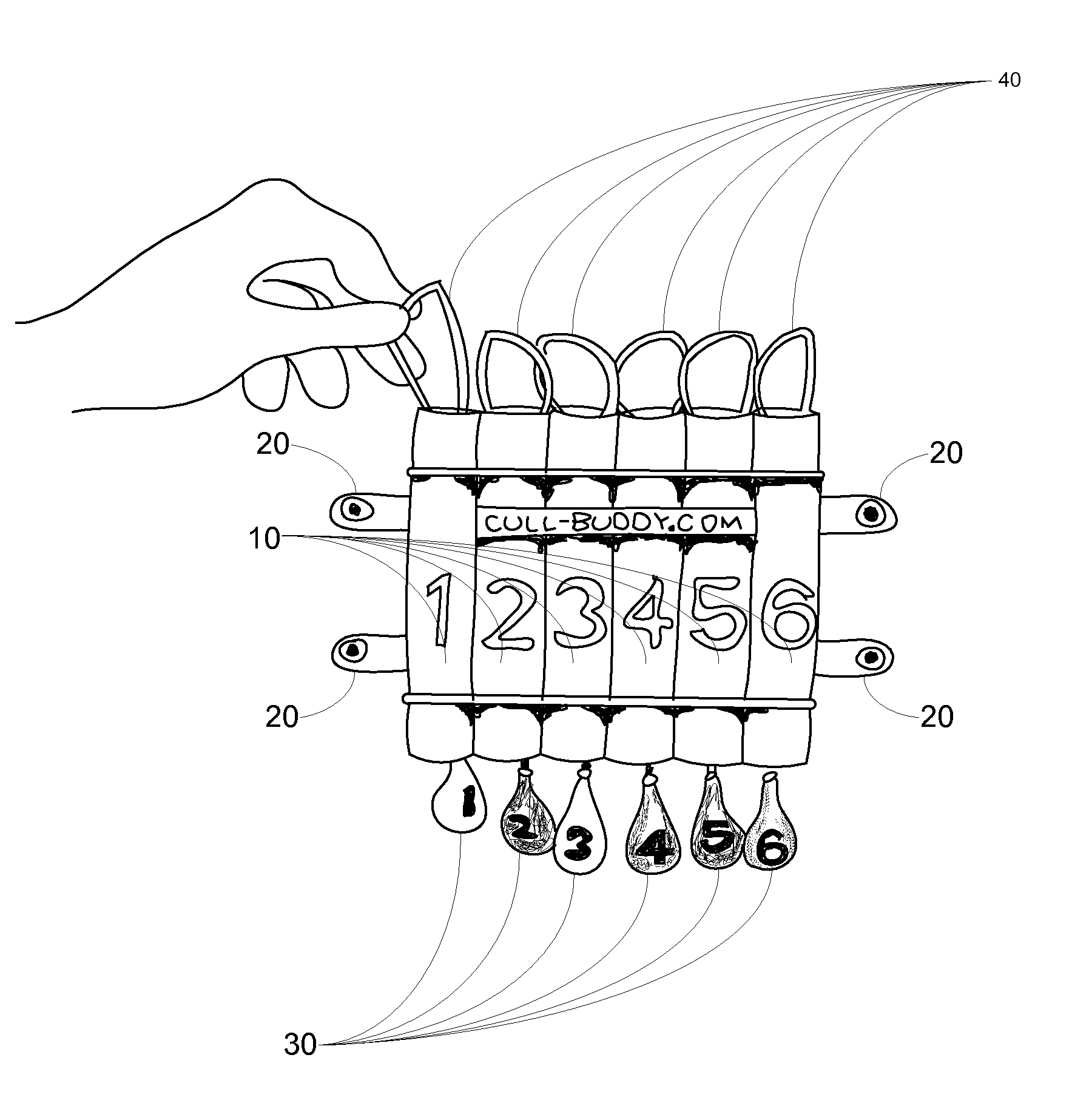
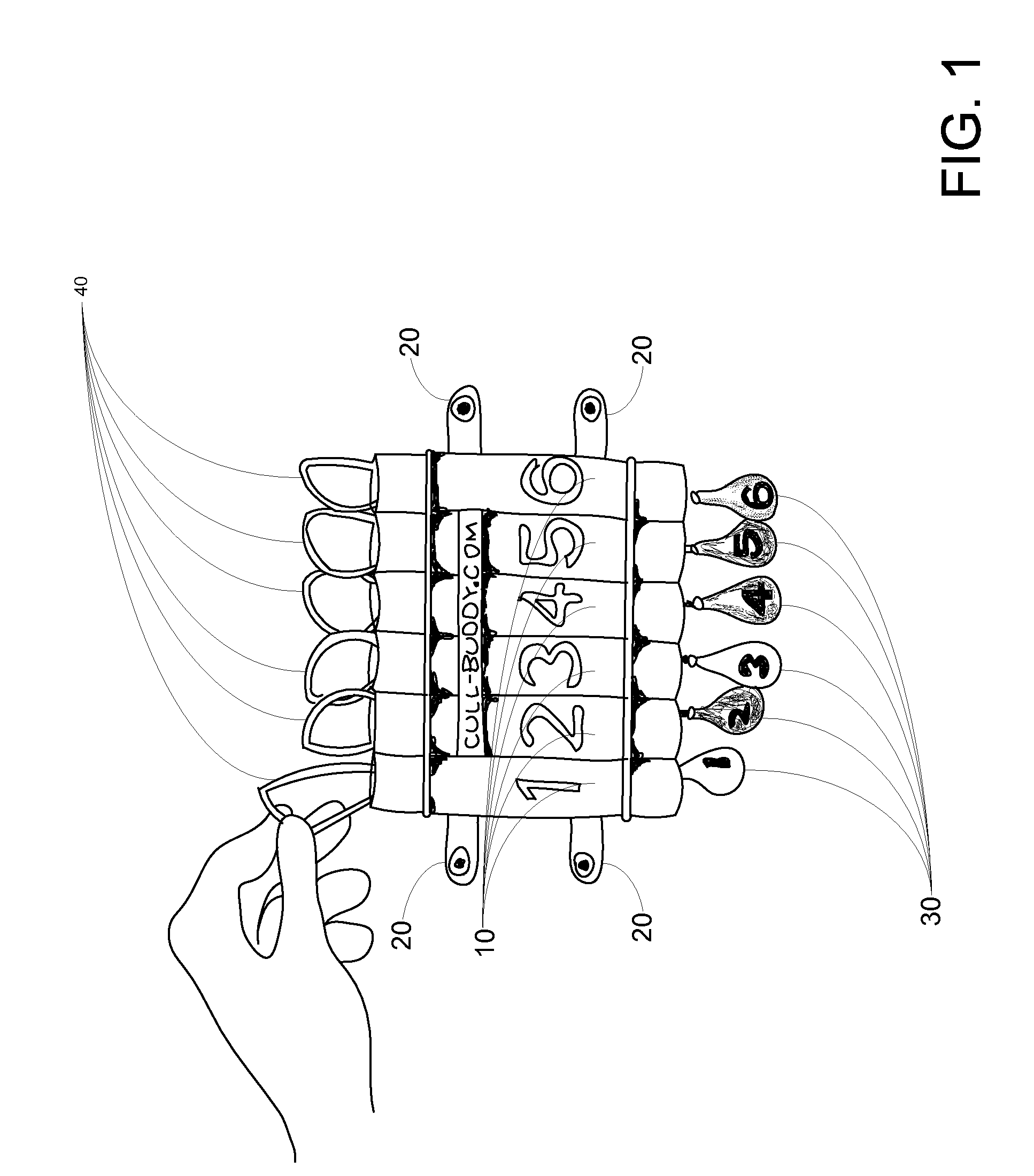
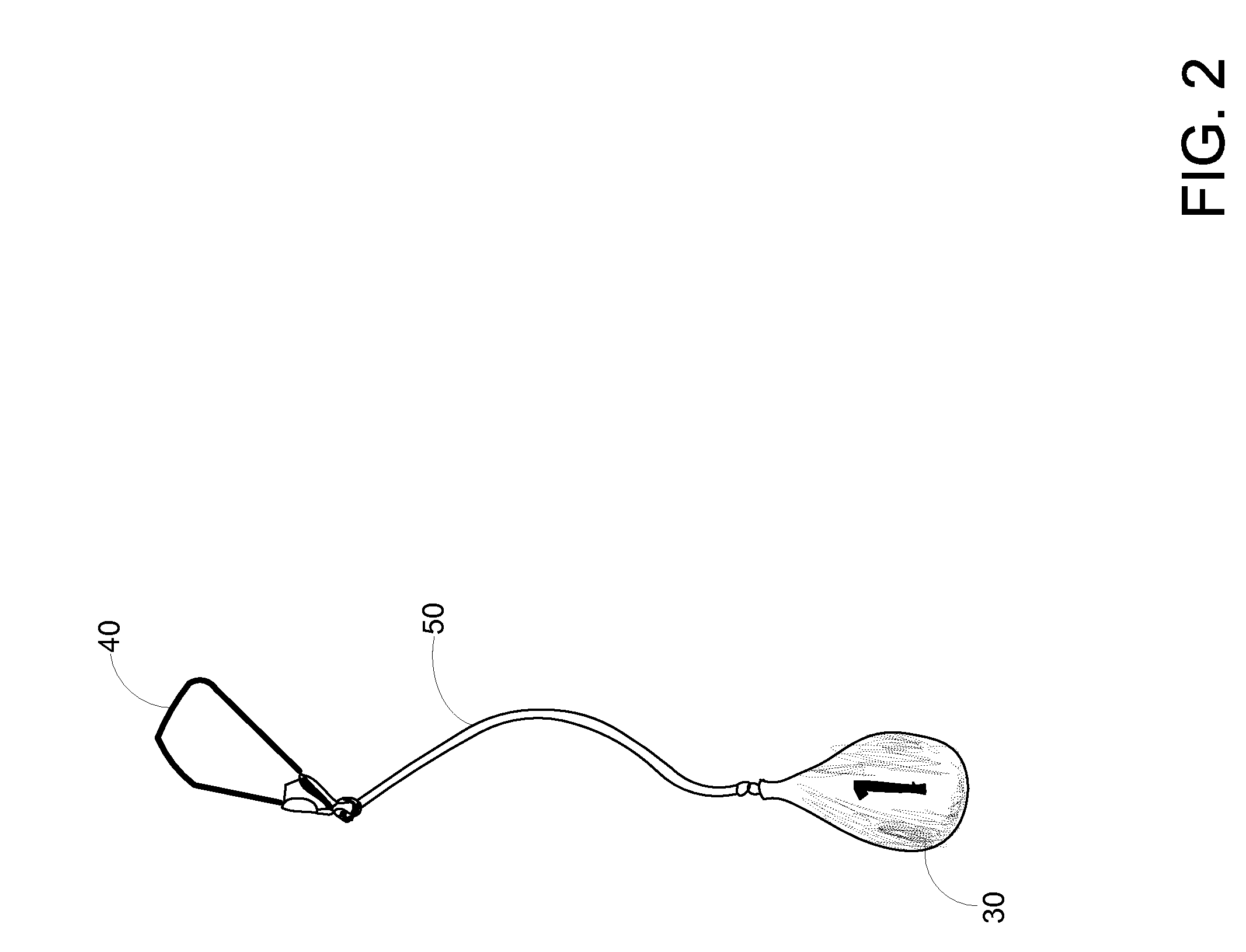
[0007]A buoy holder is an apparatus designed to organize fish culling buoys. A fish culling system that includes a buoy holder may also include, in addition to the buoy holder, a series of color-coded or sequentially numbered buoys operable to be tethered to a single fish. The primary purpose of the buoys is to provide a quick means of identification for specific fish in a tournament fisherman's live well. With identification of the smallest fish in the live well, a tournament fisherman can “cull” the fish by replacing it with a larger fish that has just been caught.

Problems solved by technology

Further, while tube bore sizes are large enough to permit the passing of a buoy float, they are small enough that the clipping apparatus comprising the opposite end of the buoy cannot.

Method used


Image

  • Buoy holder for fish culling
  • Buoy holder for fish culling
  • Buoy holder for fish culling

Examples


Embodiment Construction

[0012]The present invention, as well as features and aspects thereof, is directed towards providing a device that can hold culling buoys and provide ease of access to the same.

[0013]In general, one embodiment of the device includes multiple tubes that are laid side by side in a parallel fashion and affixed to a mounting structure or simply to each other. In one embodiment the tubes have a round cross section and are sized in such a way as to allow the buoy float and tether to be fed through the tube but that will not allow the clipping apparatus at the end of the culling buoy to pass through the interior diameter of the tube. However, it will be appreciated that the device can use a variety of tube shapes and still embody aspects of the present invention.

[0014]The device can be tooled, machined, cast or assembled from parts and be made out of a variety of materials including all varieties of plastics, metals and wood, as well as any combination thereof.

[0015]In a particular embodime...


PUM


Abstract

A culling buoy holder that includes multiple tubes laid side by side in a parallel fashion and affixed to a mounting structure or to each other. The tubes are sized in length and diameter such that a culling buoy may be inserted down through the bore of a tube, with a float first orientation, until the float dangles below the lower open end of the tube. Further, while tube bore sizes are large enough to permit the passing of a buoy float, they are small enough that the clipping apparatus comprising the opposite end of the buoy cannot pass. Advantageously, each buoy, once inserted through an individual tube of the buoy holder, is effectively separated from other buoys as it securely hangs in its individual tube.

Description

CROSS-REFERENCE TO RELATED APPLICATIONS[0001]This application is being filed under 35 USC 111 and 37 CFR 1.53(b) and claims the benefit of the filing date of the United States Provisional Application for patent that was filed on Oct. 23, 2007 and assigned Ser. No. 60 / 981,860, which is also herein incorporated by reference in its entirety.BACKGROUND OF THE INVENTION[0002]You can't catch a fish unless your hook is in the water, or so the saying goes. Professional fishermen can take that adage one step further—that is you can't make money catching fish unless your hook is in the water. Professional fishing circuits are highly competitive and the difference between finishing a tournament in the money versus just spending a lot of money to be in a tournament often comes down to the amount of time during tournament hours that a fisherman is able to devote to the business of fishing. Exercises such as tying on new baits, modifying equipment, fiddling with trolling motors and untangling mar...

Claims


Application Information

Patent Timeline
Patent Type & Authority Applications(United States)
IPC IPC(8): A01K97/00
CPCA01K97/00A01K97/20A01K97/06
Inventor MULLINS, JEFFERY L.
Owner MULLINS JEFFERY L
Learn More