
Diagnosability system: flood control

a flood control and diagnostic data technology, applied in the field of system maintenance and diagnosis, can solve the problems of cumbersome sending such a large volume of data to the diagnosis site, adversely affecting the availability of system performance, resources, reliability,

Active Publication Date: 2009-04-23
ORACLE INT CORP
View PDF99 Cites 55 Cited by
  • Summary
  • Abstract
  • Description
  • Claims
  • Application Information

AI Technical Summary

Benefits of technology

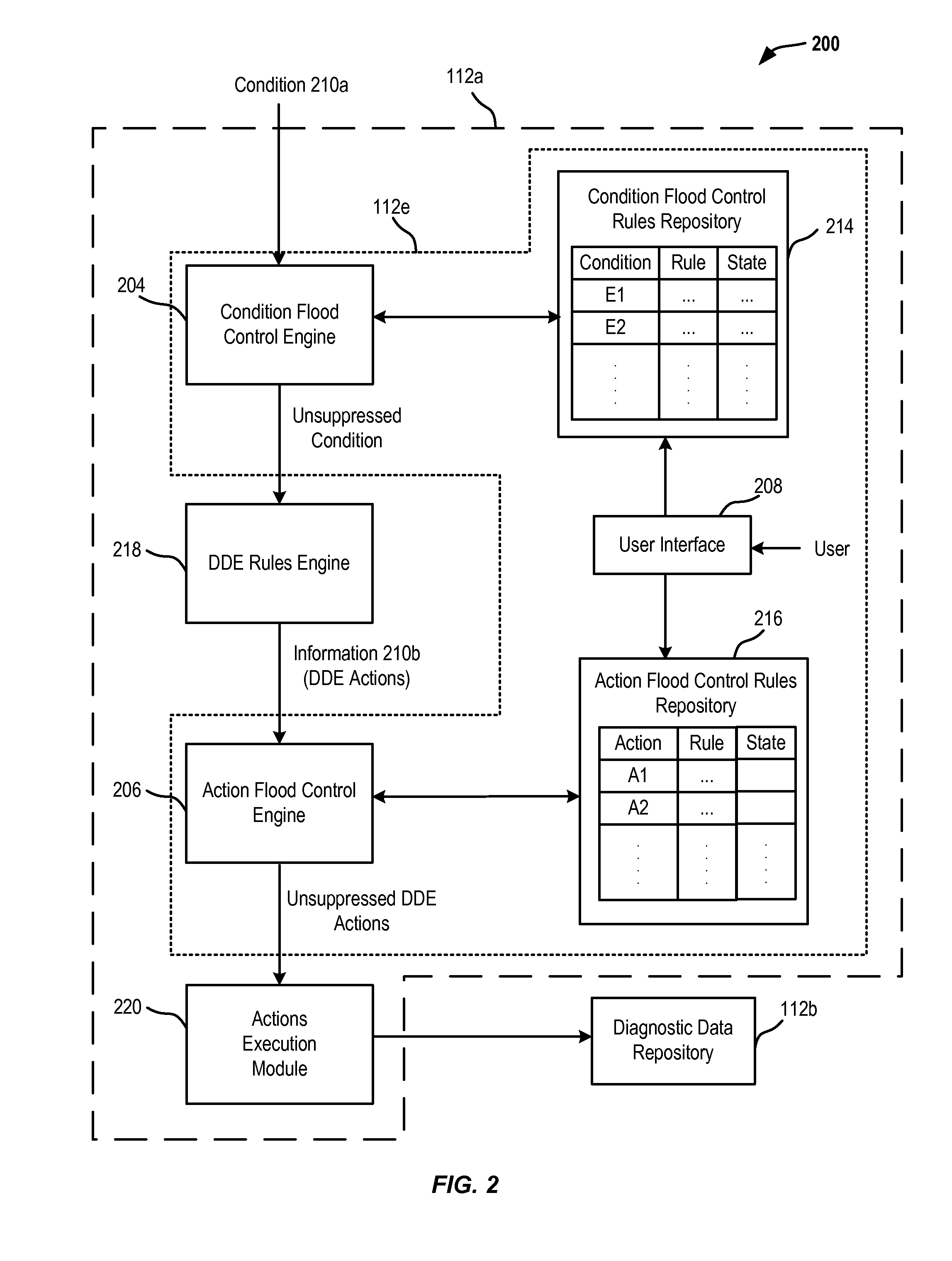
[0023]In one embodiment, the second rule may specify that execution of the diagnostic action is to be suppressed for the first N occurrences of the diagnostic action within a second time interval and execution of the diagnostic action is allowed for the (N+1)th occurrence to the (N+L)th occurrence of the diagnostic action within the second time interval, wherein N and L are both equal to or larger than 0. The second rule may specify a number of times that execution of the diagnostic action is allowed within a time interval. The second rule may be user-configurable.

Problems solved by technology

As a result, a repeatable failure or error condition in the system such as a corrupted storage media, a hardware failure, or other bugs in the system may cause the system to collect large amounts of diagnostic data in a relatively short period of time constituting a flood of diagnostic data.
Such a flood of diagnostic data may adversely impact available system performance, resources, and reliability.
Sending such a large volume of data to the diagnosis site is cumbersome, time consuming, and expensive.
Further, the larger the size of the diagnostic data, the longer it takes to analyze the diagnostic data to identify relevant pieces of data for analyzing a particular problem.
These techniques generally stop all diagnostic data gathering when a predefined storage limit is reached or exceeded.
Due to the complete stoppage of diagnostic data gathering when such a predefined storage limit is reached, diagnostic data that is relevant for diagnosis may not be gathered.
Further, diagnostic data may not be gathered for future error conditions.
As a result, using existing solutions, the diagnostic data that is gathered for the monitored system may not be sufficient to diagnose the failure or error condition completely, increasing the time-to-resolution in solving system failures.

Method used


Image

  • Diagnosability system:  flood control
  • Diagnosability system:  flood control
  • Diagnosability system:  flood control

Examples


Embodiment Construction

[0031]In the following description, for the purposes of explanation, specific details are set forth in order to provide a thorough understanding of the invention. However, it will be apparent that the invention may be practiced without these specific details.

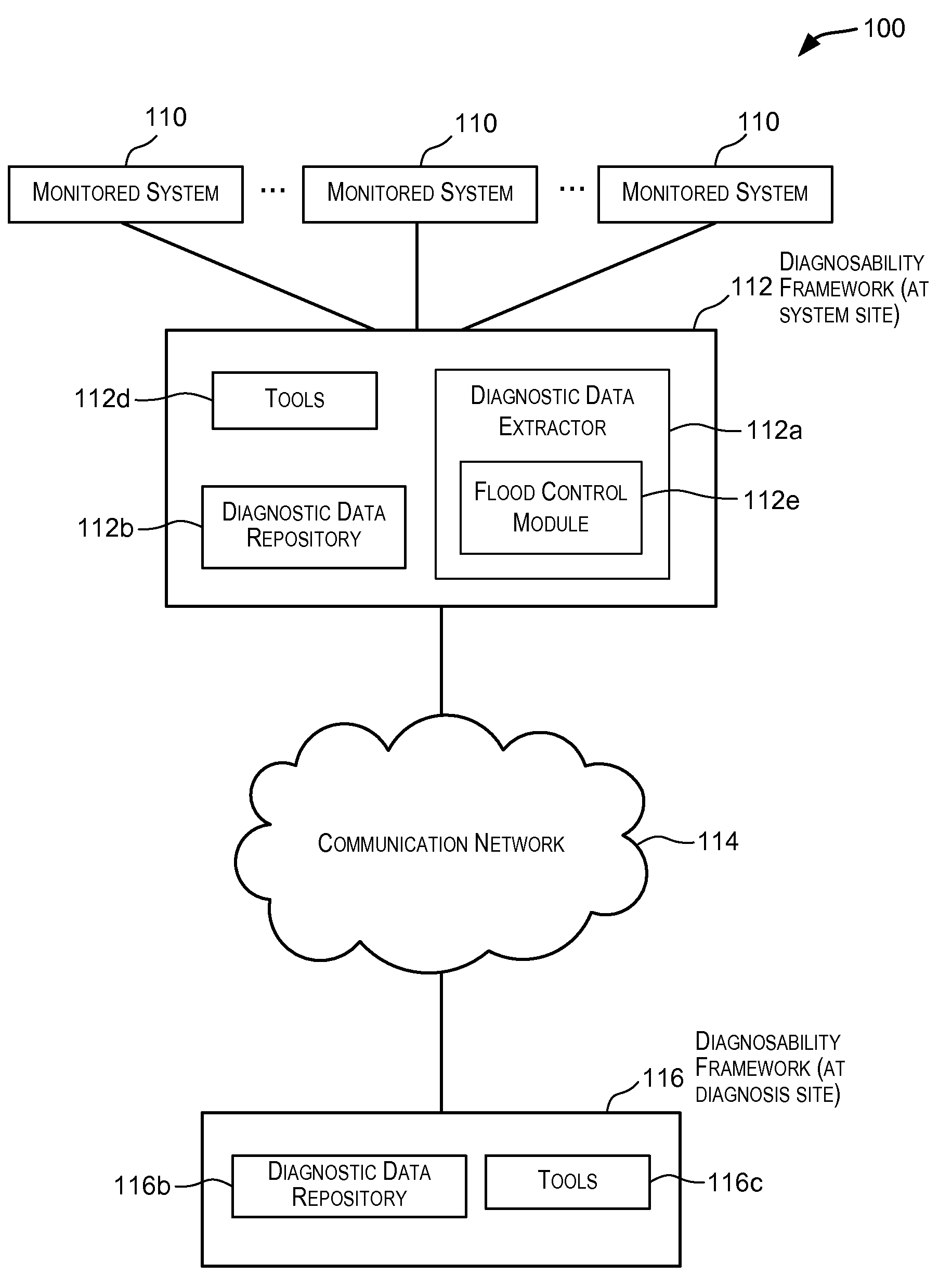
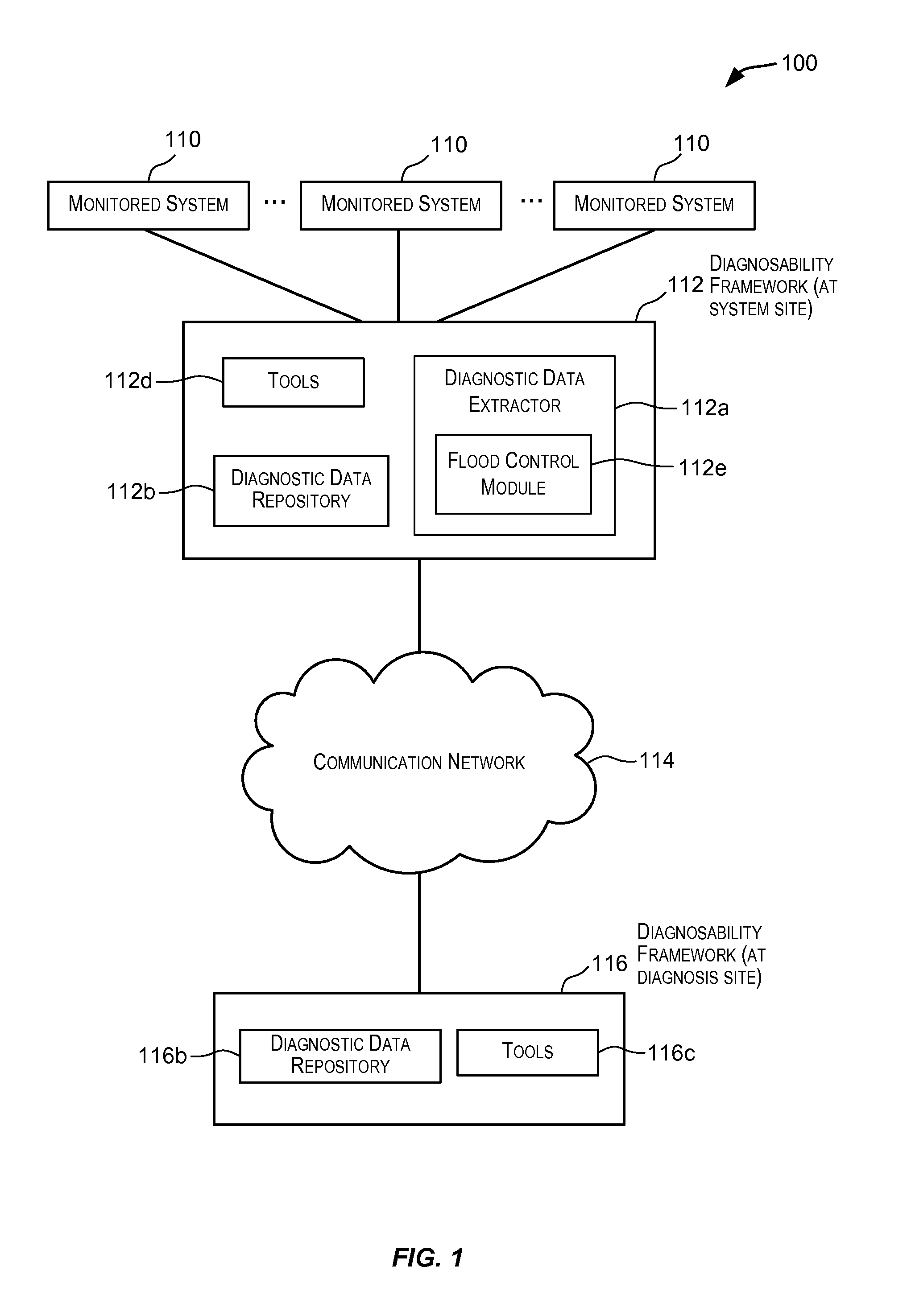
[0032]Embodiments of the present invention provide techniques for controlling collection of diagnostic data in a monitored system. A set of flood control rules are configured for the monitored system for controlling the gathering of diagnostic data in the monitored system. The set of flood control rules may include one or more default flood control rules. The set of flood control rules are user-configurable enabling the user of the monitored system to set policies for dynamically controlling gathering of diagnostic data for the monitored system. In one embodiment, diagnostic data gathering is controlled based upon a number of previous occurrences of a condition in some predefined or user-configured time frame that triggers diagn...


PUM


Abstract

Techniques for controlling collection of diagnostic data in a monitored system. A set of flood control rules are configured for the monitored system for controlling the gathering of diagnostic data in the monitored system. The set of flood control rules may include one or more default flood control rules. The set of flood control rules are user-configurable enabling the user of the monitored system to set policies for dynamically controlling gathering of diagnostic data for the monitored system. In one embodiment, diagnostic data gathering is controlled based upon a number of previous occurrences of a condition in some predefined or user-configured time frame that triggers diagnostic data gathering and / or a number of previous executions of an action performed in some predefined or user-configured time frame responsive to the condition in the monitored system.

Description

CROSS-REFERENCES TO RELATED APPLICATIONS[0001]This application claims the benefit and priority under 35 U.S.C. 119 (e) of U.S. Provisional Application Ser. No. 60 / 981,456, filed 19 Oct. 2007, entitled DIAGNOSABILITY FRAMEWORK, the contents of which are herein incorporated by reference in their entirety for all purposes.[0002]This application also incorporates by reference for all purposes the entire contents of the following related and commonly-assigned non-provisional applications, all filed concurrently with the present application:[0003](1) U.S. application Ser. No. ______ (Atty. Docket No. 021756-043700US) entitled DIAGNOSABILITY SYSTEM;[0004](2) U.S. application Ser. No. ______ (Atty. Docket No. 021756-043710US) entitled RULE-BASED ENGINE FOR GATHERING DIAGNOSTIC DATA;[0005](3) U.S. application Ser. No. ______ (Atty. Docket No. 021756-043711US) entitled GATHERING CONTEXT INFORMATION USED FOR ACTIVATION OF CONTEXTUAL DUMPING;[0006](4) U.S. application Ser. No. ______ (Atty. Doc...

Claims


Application Information

Patent Timeline
Patent Type & Authority Applications(United States)
IPC IPC(8): G06F19/00G06F15/00
CPCG06F11/0748G06F11/0778H04L41/16H04L41/0681G06F11/0781
Inventor SARIG, YAIRDAGEVILLE, BENOITFALLEN, MARCUSMYSORENAGARAJARAO, AJITH KUMARDIAS, KARLRAMACHER, MARKNGAI, GARY
Owner ORACLE INT CORP
Learn More