
Device and method for controlling robot arm, robot and program

Active Publication Date: 2009-04-23
PANASONIC CORP
View PDF8 Cites 90 Cited by
  • Summary
  • Abstract
  • Description
  • Claims
  • Application Information

AI Technical Summary

Benefits of technology

[0012]According to the robot arm controlling device and the robot including the robot arm controlling device the present invention, the mechanical impedance set value of the robot arm can be appropriately set according to the conveyance property of the object to be conveyed by the robot arm by including the object property database, the object property-concordant impedance setting means, and the impedance setting means, and thus safe robot control becomes possible where even when contacting a human, the human will not be damaged by the contact, and the robot arm will not move by such contact thus dropping the conveying object or contacting and damaging another human or another object.
[0013]Furthermore, according to the robot arm controlling method and program of the present invention, the mechanical impedance set value of the robot arm can be appropriately set and controlled according to the conveyance property of the object to be conveyed by setting the mechanical impedance set value of the robot arm based on information associated with the conveyance property of the object being conveyed by the robot arm and controlling the mechanical impedance value of the robot arm to the set mechanical impedance set value, and thus safe robot control becomes possible where even when contacting a human, the human will not be damaged by the contact, and the robot arm will not move by such contact thus dropping the conveying object or contacting and damaging another human or another object.

Problems solved by technology

However, in the conventional controlling device, the restoration force is merely made small when large force is applied to the robot arm, and thus in a case where the robot arm grips a tray and an object is placed on the tray, the robot arm may move when the robot arm and a human contact, thereby tilting the tray and dropping the object placed on the tray.
Furthermore, if the restoration force is merely made small, in a case where the robot arm is gripping a hard object or a pointed object, the hard object or the pointed object may move through contact with a human, thereby hitting and damaging the human who has contacted the robot arm, another human nearby, or other objects such as furniture.

Method used


Image

  • Device and method for controlling robot arm, robot and program
  • Device and method for controlling robot arm, robot and program
  • Device and method for controlling robot arm, robot and program

Examples


first embodiment

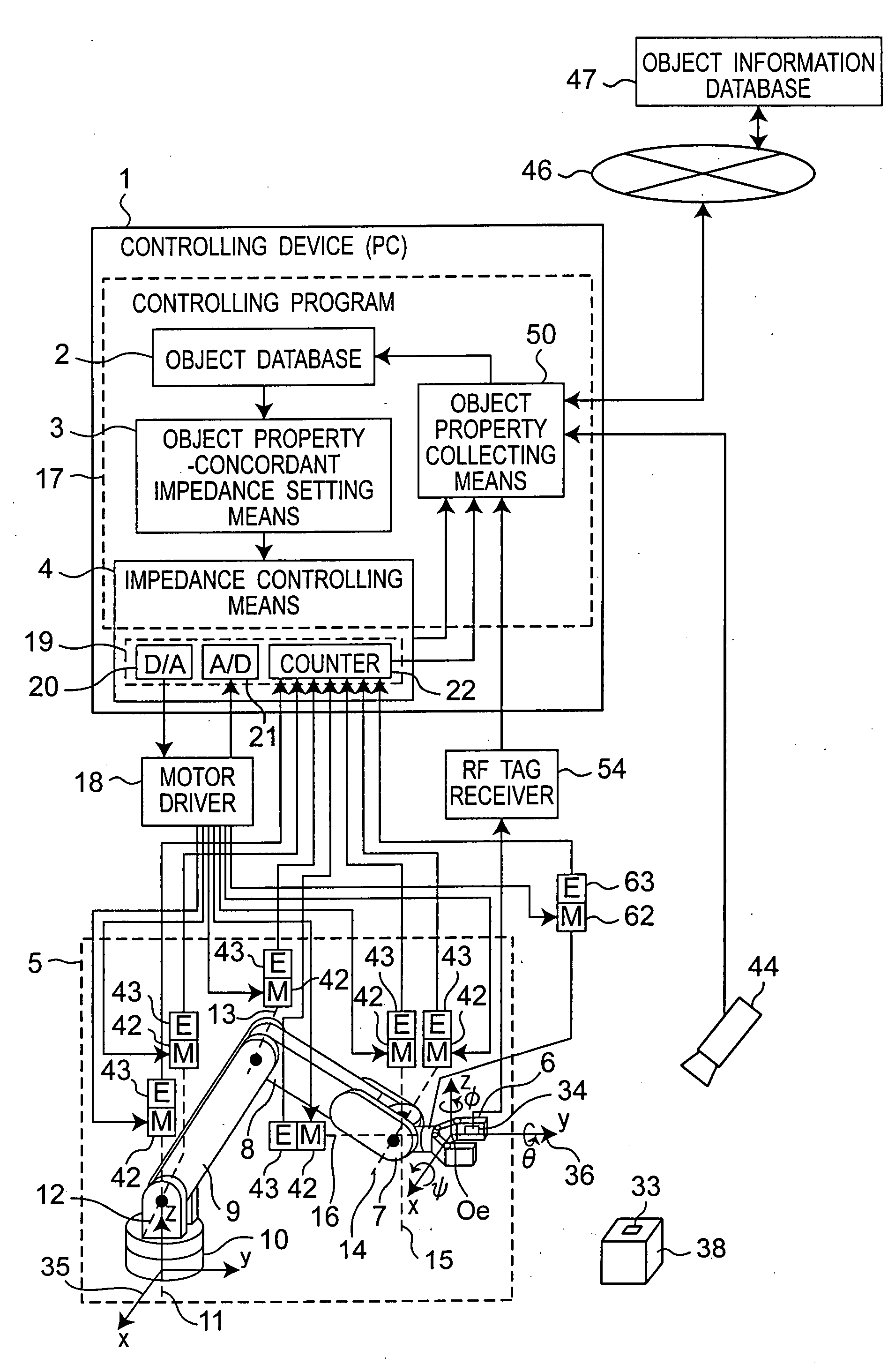
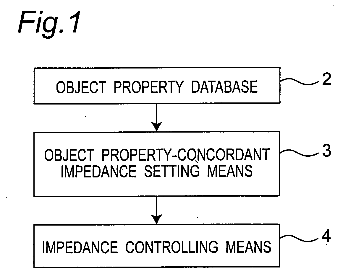
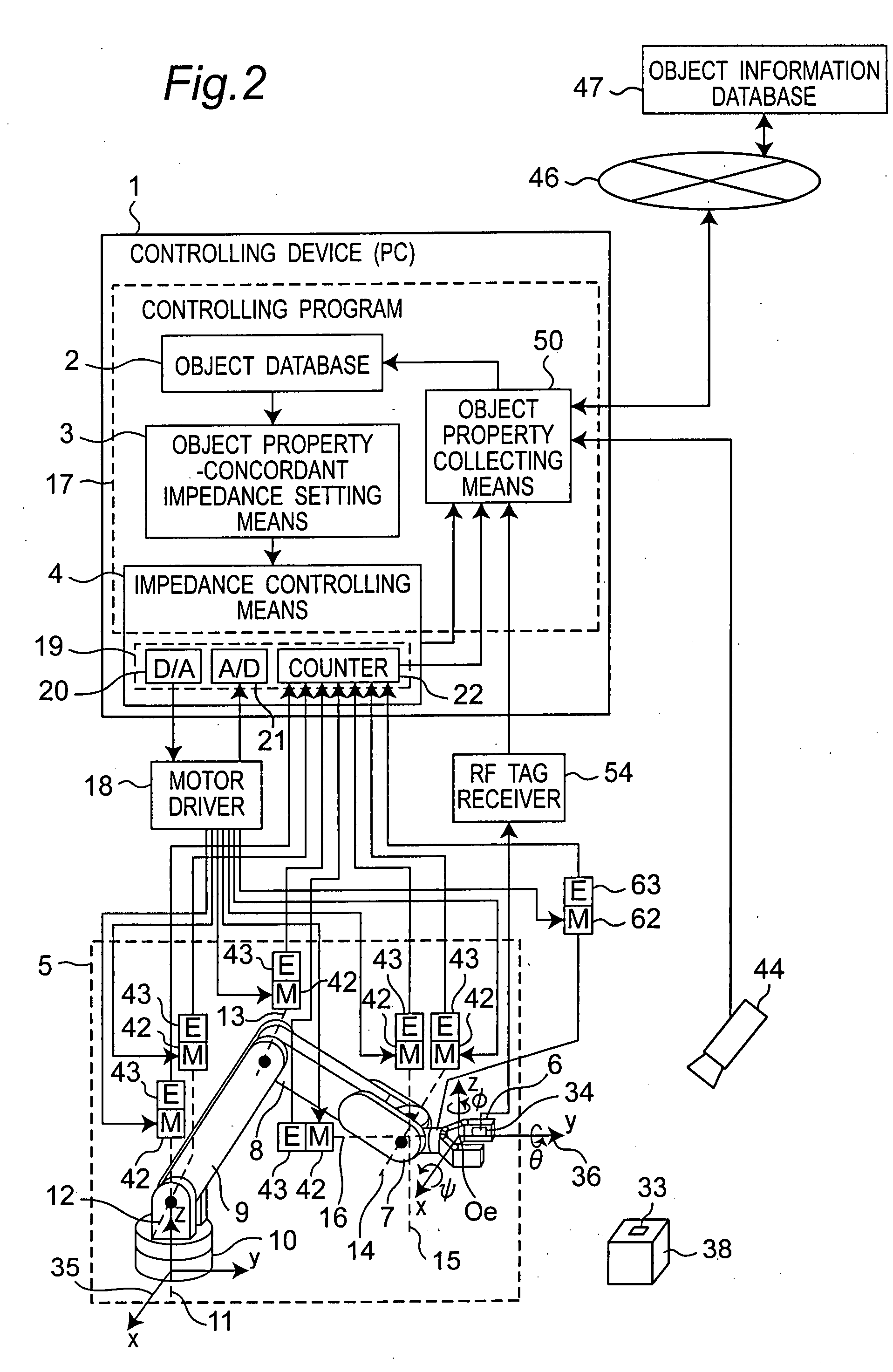
[0057]FIG. 1 is a block diagram showing the concept of a robot arm controlling device 1 according to a first embodiment of the present invention. In FIG. 1, reference numeral 2 denotes an object property database for storing conveyance property information such as gripping property information including physical property information and attribute information as an example of object property data of a conveying object to be conveyed by a robot arm 5, as described later, such as an object (gripping object) 38 to be conveyed while being gripped, the database has a function of transmitting the property data of the object 38 to an object property-concordant impedance setting means 3 when the object 38 to be gripped is specified.

[0058]The physical property information is property information that is defined physically, in terms of physical properties, geometrically such as a shape, a size (dimension), weight or a temperature of the object, as examples.

[0059]The attribute information of th...

second embodiment

[0138]The basic configuration of a robot arm controlling device according to a second embodiment of the present invention is similar to that in the first embodiment shown in FIGS. 1 and 2, and thus the description on the common parts will be omitted, and only the different part will be described below in detail.

[0139]FIG. 8 is a view explaining a gripping rule table of the object property database 2. In addition to the property list 30 shown in FIG. 4, the object property database 2 includes a gripping rule table 31 in which restricting condition information of the position and orientation of the object is described as shown in FIG. 8. Items of position maintenance, orientation maintenance, and height maintenance are provided in the gripping rule table 31, and the numerical value of 1 or 0 is recorded in advance for each item.

[0140]When the item of orientation maintenance is 1, information on orientation restricting condition of fixing the object without moving the orientation is in...

third embodiment

[0155]The basic configuration of the controlling device according to a third embodiment of the present invention is similar to that in the second embodiment, and thus the description on the common parts will be omitted, and only the different parts will be hereinafter described in detail.

[0156]FIG. 11 is a block diagram showing a configuration of an impedance controlling means 4A of a robot arm controlling device according to a third embodiment of the present invention. 32 denotes a directional impedance adjusting means having a function of adjusting the feedback gains of the position error compensating means 27 by directions based on the mechanical impedance set value set by the object property-concordant impedance setting means 3 and the gripping rule table 31 of the object property database 2.

[0157]In the object property-concordant impedance setting means 3 of the impedance controlling means 4A of the controlling device according to the third embodiment of the present invention, ...


PUM


Abstract

In a robot arm controlling device, a mechanical impedance set value of the arm is set by an object property-concordant impedance setting device based on information of an object property database in which information associated with properties of an object being gripped by the arm is recorded, and a mechanical impedance value of the arm is controlled to the set mechanical impedance set value by an impedance controlling device.

Description

TECHNICAL FIELD[0001]The present invention relates to a robot arm controlling device and controlling method for controlling the robot arm of a robot such as a household robot having a possibility of physically contacting a person, a robot equipped with the robot arm controlling device, and a robot arm controlling program.BACKGROUND ART[0002]In recent years, development of household robots such as pet robots has been actively carried out, and it is expected that a more practical household robot such as a household assistant robot will be put to practical use in the future. Since the household robot must be part of the household and coexist with humans, physical contact with humans is inevitable, and is thus required to be flexible in terms of safety.[0003]To respond to such an issue, a controlling device is disclosed in Unexamined Japanese Patent Publication No. 10-329071 of patent document 1 as a background art for detecting a contacting force with a human that is applied to a robot...

Claims


Application Information

Patent Timeline
IPC IPC(8): B25J19/06
CPCB25J9/1633G05B2219/39343G05B2219/41387G05B2219/40201G05B2219/40198
Inventor OKAZAKI, YASUNAO
Owner PANASONIC CORP
Learn More