Image pickup apparatus

a technology of image pickup and telescopic body, which is applied in the field of image pickup apparatus, can solve the problems of increasing manufacturing cost, affecting image quality, and affecting the quality of image, and achieve the effect of not deteriorating the image quality

Inactive Publication Date: 2009-04-23
CANON KK
View PDF26 Cites 14 Cited by
  • Summary
  • Abstract
  • Description
  • Claims
  • Application Information

AI Technical Summary

Benefits of technology

[0016]According to aspects of the present invention, the center shift caused by the zooming operation can be corrected inexpensively without deterioration in the image quality. Moreover, when a plurality of correction modes are provided, priority may be given to center-shift correction or a pan / tilt operation.

Problems solved by technology

However, a center shift may actually occur during zooming due to mechanical variation, such as decentration of lens groups, or a deviation between mounting positions of a lens and an image pickup element.
Thus, a center shift of a screen caused by zooming has been a bottleneck in recent years.
However, either method is troublesome work and increases the manufacturing cost.
However, when the center shift is corrected by shifting the extraction position from the image pickup element as disclosed in the Japanese Patent Laid-Open No. 9-27926, an image to be captured utilizes only a part of effective pixels of the image pickup element, and hence, image quality may be deteriorated.
However, since a part of a vibration angle of the optical system for image stabilization is used for center-shift correction, an image stabilization effect and a center-shift correction effect may not be sufficiently provided.

Method used


Image

  • Image pickup apparatus
  • Image pickup apparatus
  • Image pickup apparatus

Examples


Embodiment Construction

[0023]An illustrated embodiment of the present invention is described in detail with reference to FIGS. 1 to 4.

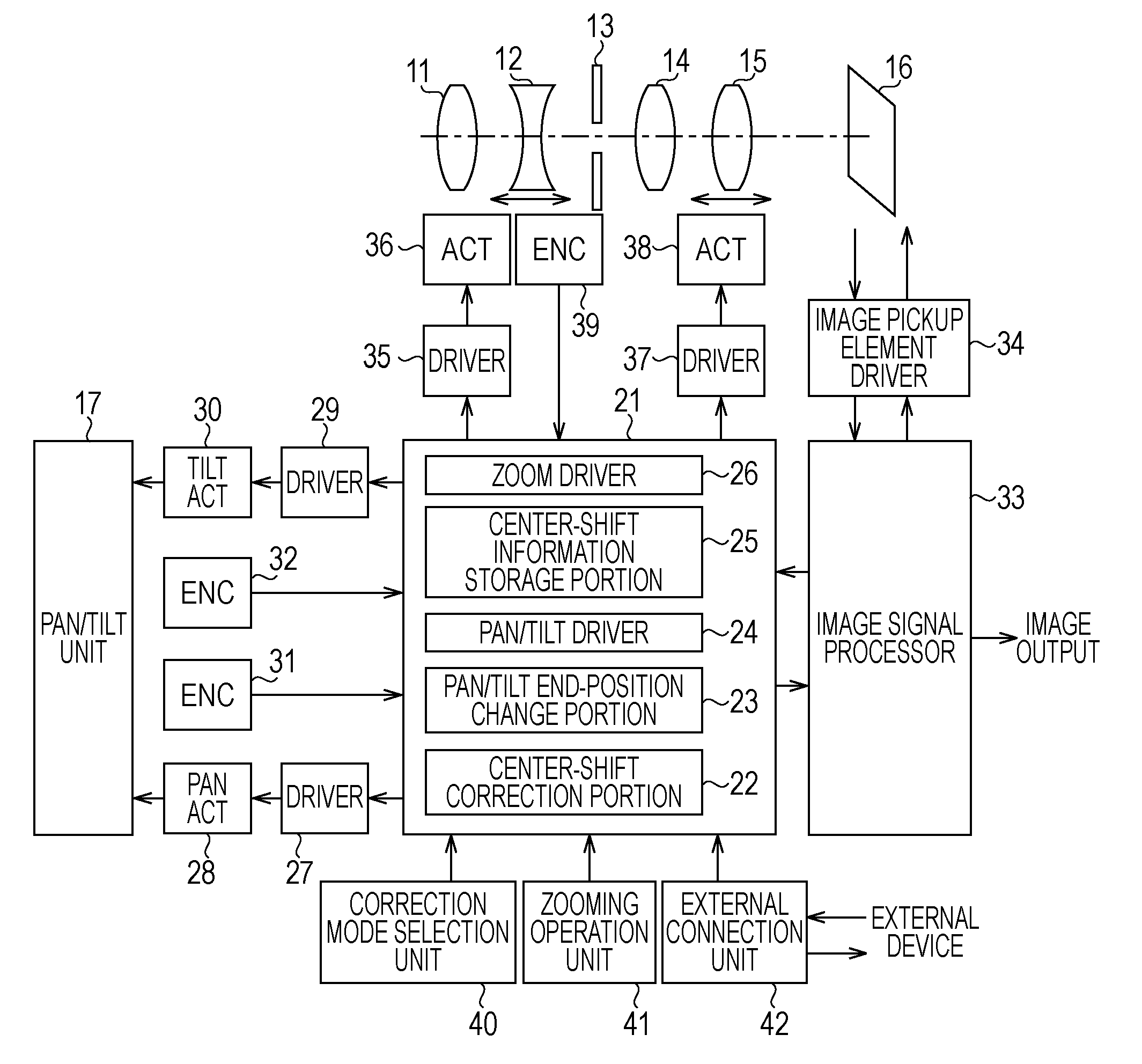
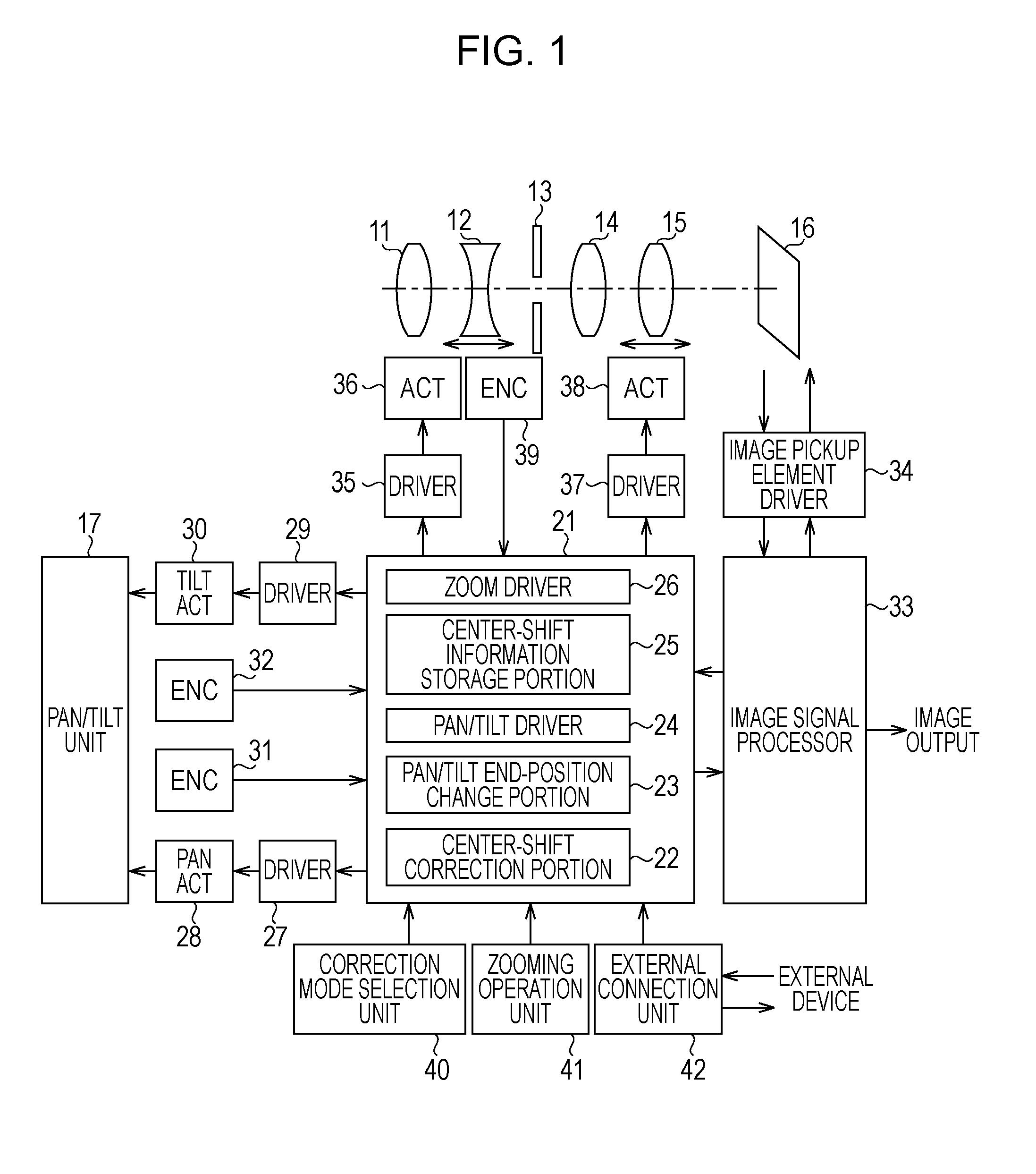
[0024]FIG. 1 is a block diagram showing a circuit configuration of an image pickup apparatus according to an embodiment of the present invention.

[0025]A front lens unit 11, a zoom lens unit 12, an aperture unit 13, a fixed lens unit 14, a focus lens unit 15, and an image pickup element 16 are arranged on an optical axis. A lens unit involves these units, and is mounted on a pan / tilt unit 17, such as a camera platform, to perform a pan operation or a tilt operation.

[0026]A control CPU 21 includes a center shift correction portion 22, a pan / tilt end-position change portion 23, a pan / tilt driver 24, a center shift information storage portion 25, and a zoom driver 26.

[0027]The output of the control CPU 21 is connected with the pan / tilt unit 17 via a driver 27, a pan actuator 28, a driver 29, and a tilt actuator 30. The position of the pan / tilt unit 17 is detected by a pan posit...


PUM


Abstract

An optical apparatus includes a zoom lens unit, a pan / tilt unit configured to at least one of pan the zoom lens unit and tilt the zoom lens unit, and a center-shift information storage portion configured to store a shift amount of an optical axis for every zooming position, and has a mechanism configured to correct a shift of the optical axis caused by zooming, by driving the pan / tilt unit by the shift amount of the optical axis stored in the center-shift information storage portion.

Description

BACKGROUND OF THE INVENTION[0001]1. Field of the Invention[0002]The present invention relates to a method of correcting misalignment of optical axes caused by zooming in an image pickup apparatus.[0003]In particular, the present invention relates to an image pickup apparatus having at least one of a pan mechanism and a tilt mechanism, for example, an image pickup apparatus capable of correcting a center shift of a captured image generated due to misalignment of optical axes of an image pickup lens system caused by zooming when zooming is optically performed.[0004]2. Description of the Related Art[0005]In recent years, a high power, high image-quality image pickup apparatus has been developed. Ideally, if optical axes of all lenses in a lens system are aligned with each other, a center shift of a screen caused by zooming does not occur. Hence, a center object at a wide-angle end would not be shifted from a center object at a telephoto end. Also, a center shift does not occur at an in...

Claims


Application Information

Patent Timeline
Patent Type & Authority Applications(United States)
IPC IPC(8): H04N7/18G03B13/00
CPCG03B13/00H04N5/23296H04N5/23206H04N5/232H04N23/661H04N23/69
Inventor YAMANAKA, TOMOAKI
Owner CANON KK
Why Eureka
Try Eureka