Eureka AIR delivers breakthrough ideas for toughest innovation challenges, trusted by R&D personnel around the world.

Method of operating a solar thermal power plant and solar thermal power plant

a technology of solar thermal power plant and solar thermal power plant, which is applied in the direction of solar thermal steam generation, instruments, lighting and heating apparatus, etc., can solve the problems of high cost of sensors and control problems

Inactive Publication Date: 2009-04-23
DEUTSCHES ZENTRUM FUER LUFT & RAUMFAHRT EV
View PDF17 Cites 27 Cited by
  • Summary
  • Abstract
  • Description
  • Claims
  • Application Information

AI Technical Summary

Benefits of technology

[0006]In accordance with the present invention, a method and a solar thermal power plant are provided, which allow non-uniform irradiation situations of the evaporator section to be effectively taken into consideration.

Problems solved by technology

Such sensors are very expensive and also entail control-related problems.

Method used


Image

  • Method of operating a solar thermal power plant and solar thermal power plant
  • Method of operating a solar thermal power plant and solar thermal power plant
  • Method of operating a solar thermal power plant and solar thermal power plant

Examples


Embodiment Construction

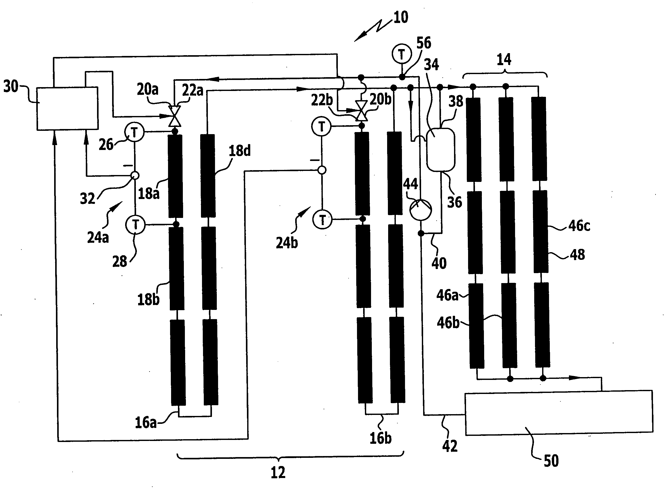
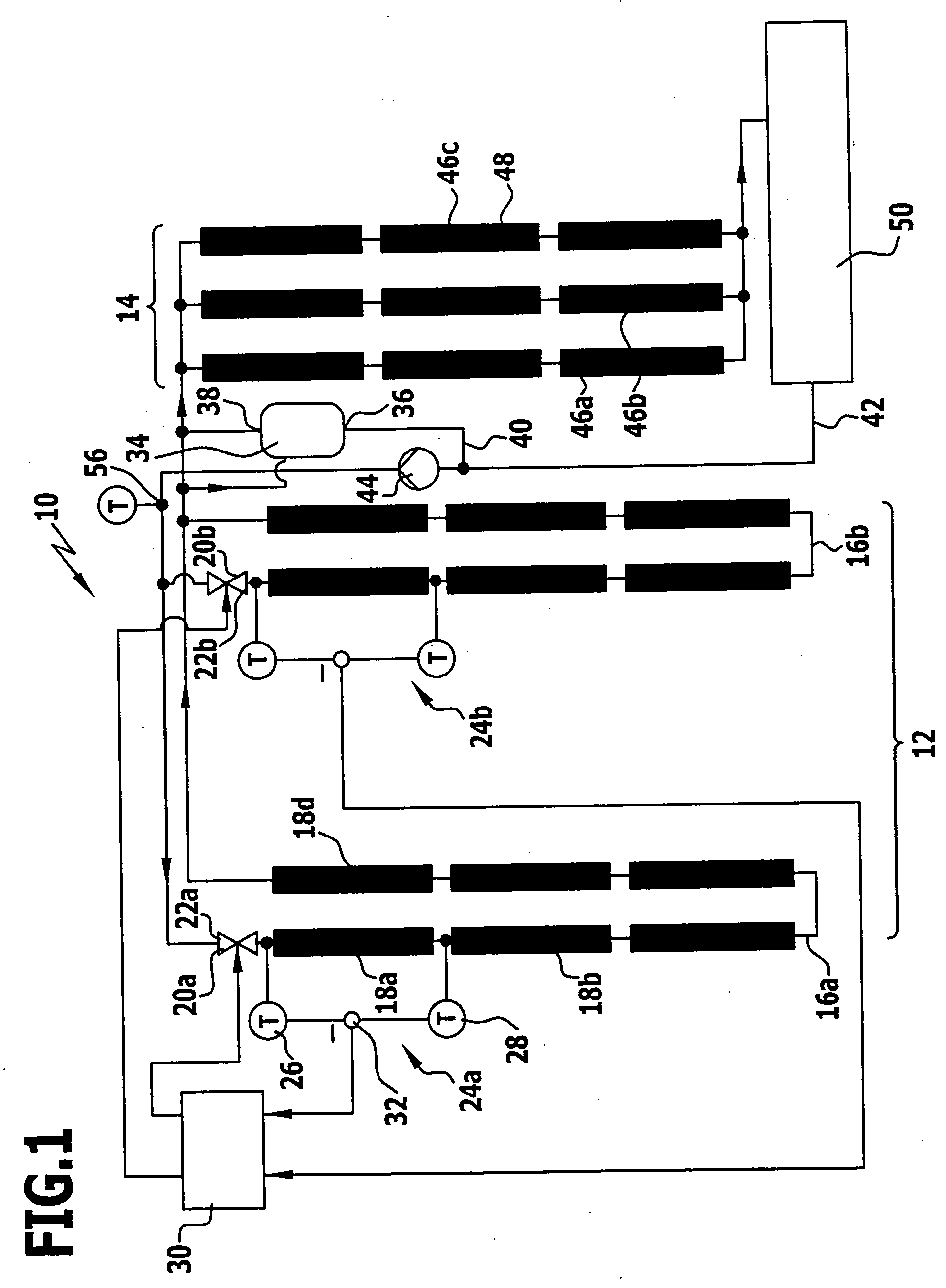
[0052]An embodiment of a solar thermal power plant according to the invention, which is shown diagrammatically in FIG. 1 and denoted there by 10, comprises an evaporator section 12 and a superheater section 14. In the evaporator section 12 liquid heat transfer medium, such as for example water, is evaporated by heat absorption from solar radiation. In the superheater section 14 the vaporous heat transfer medium coming from the evaporator section 12 is superheated.

[0053]The evaporator section 12 comprises a plurality of evaporator branches 16a, 16b etc. The evaporator branches 16a, 16b are arranged parallel; there is a parallel distribution of heat transfer medium among them.

[0054]An evaporator branch 16a, 16b in turn comprises a plurality of solar collectors 18a, 18b, . . . , 18d, which are disposed in succession (connected in series). Heat transfer medium flowing through an evaporator branch 16a, 16b has to flow through all of the solar collectors 18a, 18b, . . . , 18d of the evapo...


PUM


Abstract

In order to provide a method of operating a solar thermal power plant, in which a heat transfer medium is evaporated endothermally by solar radiation in an evaporator section, wherein the evaporator section comprises a plurality of evaporator branches, among which the heat transfer medium is distributed, in which method non-uniform radiation conditions of the evaporator section may be effectively taken into consideration, it is provided that the mass flow distribution at the evaporator section is controlled, wherein the mass flows are adjusted individually at all or a majority of the evaporator branches and a controlled variable is a variable characterizing a spatial energy rise in a respective evaporator branch in a region of the evaporator branch where the heat transfer medium has not yet evaporated.

Description

[0001]The present disclosure relates to the subject matter disclosed in German application number 10 2007 052 234.9 of Oct. 22, 2007, which is incorporated herein by reference in its entirety and for all purposes.BACKGROUND OF THE INVENTION[0002]The invention relates to a method of operating a solar thermal power plant, in which a heat transfer medium is evaporated endothermally by solar radiation in an evaporator section, wherein the evaporator section comprises a plurality of evaporator branches, among which the heat transfer medium is distributed.[0003]The invention further relates to a solar thermal power plant, comprising an evaporator section having a plurality of evaporator branches, in which heat transfer medium is evaporable endothermally by solar radiation.[0004]In solar thermal power plants a heat transfer medium is heated by solar radiation. The thermal energy of the heat transfer medium is converted (partially) into mechanical energy in one or more turbines. At one or m...

Claims


Application Information

Patent Timeline
Patent Type & Authority Applications(United States)
IPC IPC(8): F24J2/00G05D23/00
CPCF22B1/006F03G6/065Y02E10/46F22B35/083
Inventor ECK, MARKUSHIRSCH, TOBIAS
Owner DEUTSCHES ZENTRUM FUER LUFT & RAUMFAHRT EV
Why Eureka
Eureka Blog
Learn More