
Optical sensor calibration

a technology for optical sensors and calibration, applied in the direction of optical radiation measurement, instruments, ac/dc measuring bridges, etc., can solve the problems of inefficiency in production, measurement accuracy, and measurement accuracy that cannot be determined by and the calibration does not take into account the situation in which the sensor is used

Inactive Publication Date: 2009-04-23
RPX CORP
View PDF8 Cites 15 Cited by
  • Summary
  • Abstract
  • Description
  • Claims
  • Application Information

AI Technical Summary

Benefits of technology

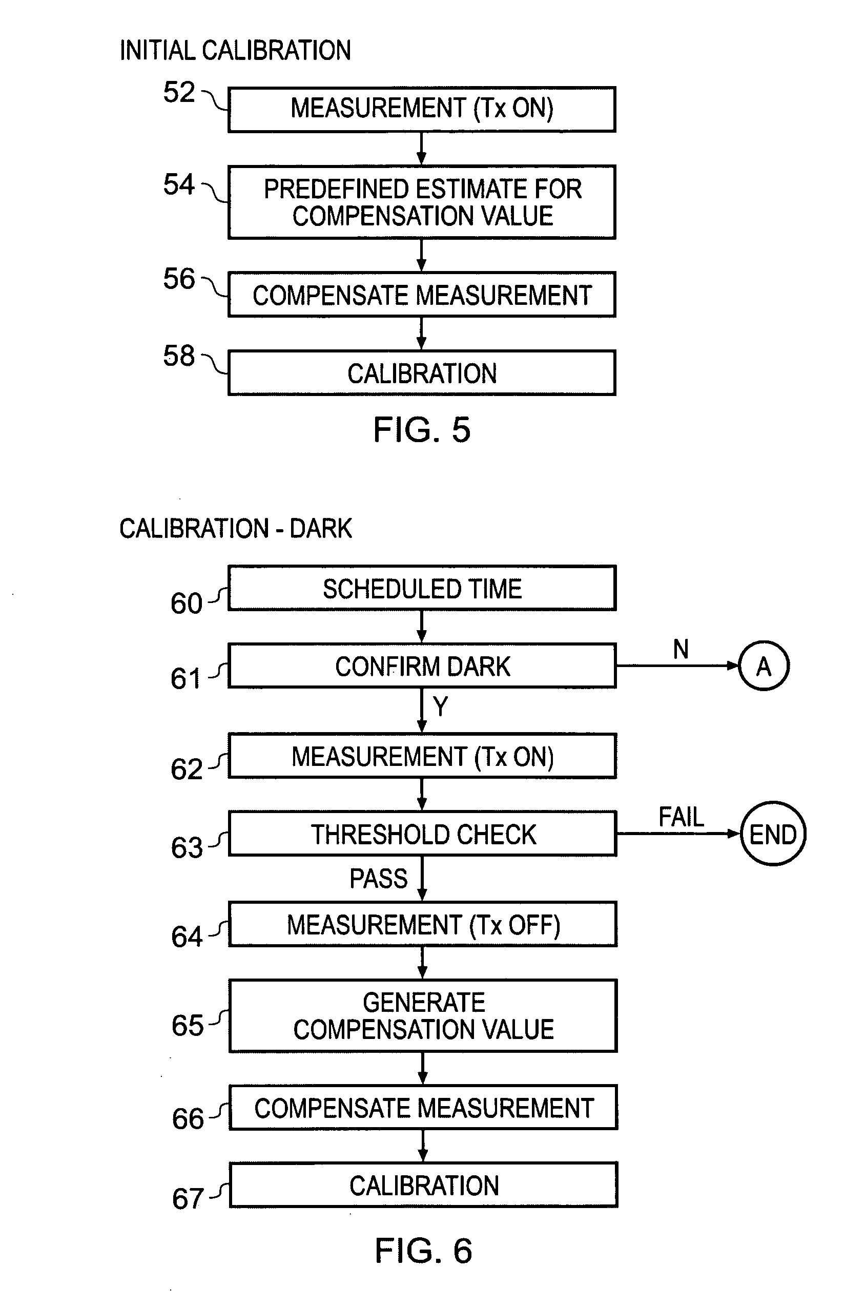
[0007]The process of determining the systematic error is moved from the production line into the apparatus so that it occurs during use. The term ‘during use’ or ‘in use’ refers to the period post production when the apparatus can be used, whether or not it is actually being used by a user. This is made possible by the test, in use, which prevents inappropriate measurements being used to determine the systematic error.
[0013]The apparatus may comprise a protective screen in an optical path between the optical transmitter and the optical receiver whereby scheduled re-calibration compensates for progressive wear to the protective screen and for the presence of impurities such as dust, oil etc.

Problems solved by technology

However, this will typically require the sensor to have some non-volatile memory for storing the calibration data and this is undesirable as it raise the size, cost and complexity of the sensor.
Furthermore, such calibration does not take into account the situation in which the sensor is used.
Whenever a measurement is taken at the optical sensor in-situ the measurement includes a ‘signal’ from a target and a ‘systematic error’.
This leads to inefficiencies in production.

Method used


Image

  • Optical sensor calibration
  • Optical sensor calibration
  • Optical sensor calibration

Examples


Embodiment Construction

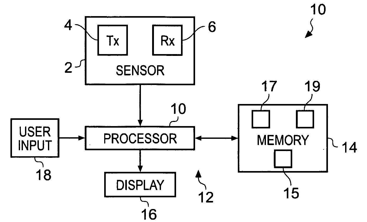
[0006]According to various embodiments of the invention there is provided an apparatus comprising: an optical sensor comprising an optical transmitter and an optical receiver; and a calibration system configured to change calibration of the sensor when a measurement taken at the optical receiver, while an optical transmitter is on and the apparatus is in use, passes a test.

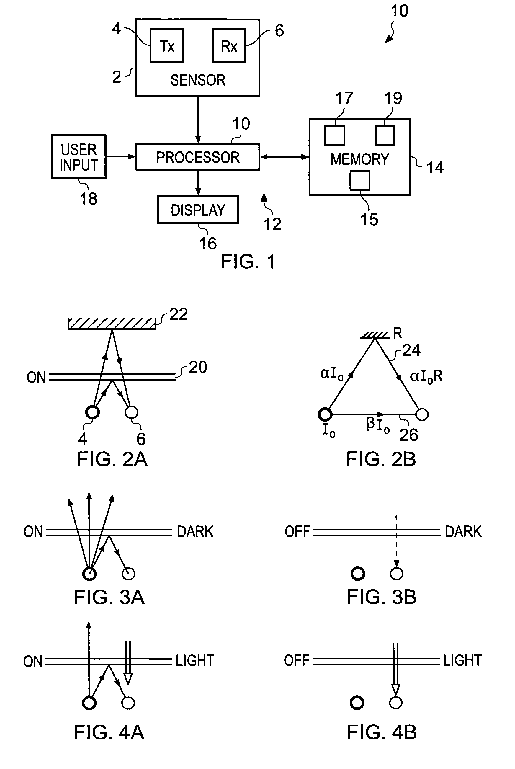
[0007]The process of determining the systematic error is moved from the production line into the apparatus so that it occurs during use. The term ‘during use’ or ‘in use’ refers to the period post production when the apparatus can be used, whether or not it is actually being used by a user. This is made possible by the test, in use, which prevents inappropriate measurements being used to determine the systematic error.

[0008]The apparatus, in use, is therefore able to calibrate the sensor automatically when it is in a normally occurring environment, such as on a night stand in a dark bedroom, without additional spe...


PUM


Abstract

An apparatus including: an optical sensor comprising an optical transmitter and an optical receiver; and a calibration system configured to change calibration of the sensor when a measurement taken at the optical receiver, while the optical transmitter is on and the apparatus is in use, passes a test.

Description

FIELD OF THE INVENTION[0001]Embodiments of the present invention relate to optical sensor calibration.BACKGROUND TO THE INVENTION[0002]Many optical sensors need to be calibrated.[0003]It may be possible to calibrate a sensor when it is manufactured. However, this will typically require the sensor to have some non-volatile memory for storing the calibration data and this is undesirable as it raise the size, cost and complexity of the sensor. Furthermore, such calibration does not take into account the situation in which the sensor is used.[0004]It may be possible to calibrate a sensor when it is in-situation within an apparatus, for example, as part of the production line for the apparatus. Whenever a measurement is taken at the optical sensor in-situ the measurement includes a ‘signal’ from a target and a ‘systematic error’. The production line may need to be adapted so that multiple different reference targets, for example separate white and black targets, are introduced to determi...

Claims


Application Information

Patent Timeline
Patent Type & Authority Applications(United States)
IPC IPC(8): G01R17/14G12B13/00
CPCG12B13/00
Inventor PORJO, NIKO SANTERI
Owner RPX CORP
Learn More