
Dynamic Selection Between Active and Passive Probing in Computer Network

a computer network and dynamic selection technology, applied in the field of computer network probing, can solve problems such as consumption of network resources

Active Publication Date: 2009-04-16
CISCO TECH INC
View PDF16 Cites 15 Cited by
  • Summary
  • Abstract
  • Description
  • Claims
  • Application Information

AI Technical Summary

Problems solved by technology

Passive probing may be appropriate only for certain types of traffic and may require particular circumstances to function adequately, while active probing consumes network resources requiring, as it does, additional probe test signals to be processed by various components.

Method used


Image

  • Dynamic Selection Between Active and Passive Probing in Computer Network
  • Dynamic Selection Between Active and Passive Probing in Computer Network
  • Dynamic Selection Between Active and Passive Probing in Computer Network

Examples


example embodiments

DESCRIPTION OF EXAMPLE EMBODIMENTS

Overview

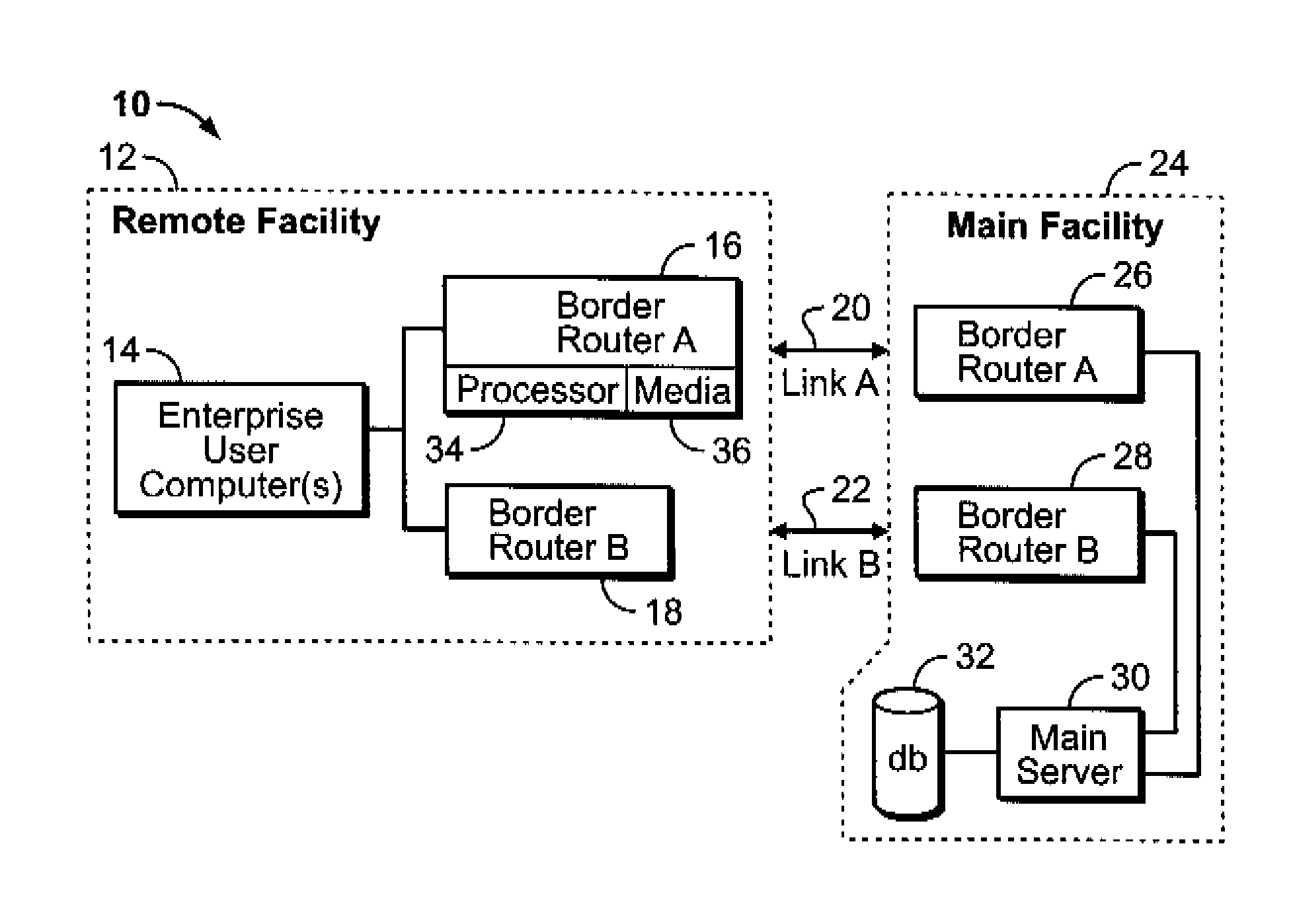
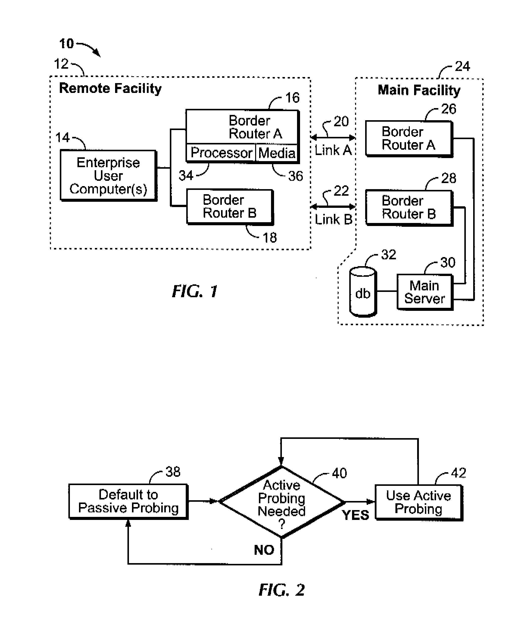
[0015]Referring initially to FIG. 1, a system is shown, generally designated 10, which can include one or more remote facilities 12 (only one facility 12 shown for clarity) that can include one or more enterprise user computers 14 (only a single user computer 14 shown for clarity). The user computer 14 communicates through one or more border routers 16, 18, each of which is typically associated with a respective communication link 20, 22. The links 20, 22 may be thought of in non-limiting embodiments as primary and secondary communication links between the user computer 14 and a main facility 24, which, as shown, can include border routers 26, 28 respectively corresponding to the border routers 16, 18 of the remote facility and communicating with their respective corresponding border routers over respective links 20, 22 as shown. It is to be understood that only one side of the communication path (remote facility 12 or main facility 24) need...


PUM


Abstract

In one embodiment, during network operation, it is dynamically determined whether to change from passive probing of communication path metrics to active probing of communication path metrics.

Description

I. FIELD OF THE INVENTION[0001]The present invention relates generally to probing in computer networks to ascertain network performance.II. BACKGROUND OF THE INVENTION[0002]Large enterprises often tie geographically remote sites to central computers. As an example, a banking enterprise may provide communication between a central data center that holds bank customer records and each of potentially thousands of branch banks.[0003]To improve communication reliability and load balancing, “multi-homing” may be used in which more than a single communication link can connect network components. Various technologies, sometimes referred to collectively as “optimal exit link selection”, can be used in selecting which particular link is used at a given time, with the decision being reflected in the selection of an “exit link” typically at a border router in the network. The goals may be, e.g., to improve network performance, optimize load distribution, and lower costs for Internet connections....

Claims


Application Information

Patent Timeline
IPC IPC(8): G06F11/00
CPCH04L43/12H04L41/5009
Inventor AKHTER, AAMERBLAIR, DANA
Owner CISCO TECH INC
Learn More