
Image processing apparatus, method, and program

a technology of image processing and motion vector, applied in the direction of color signal processing circuits, instruments, television systems, etc., can solve the problems of no expected image obtained by image reconstruction, high-resolution image degrade, and sharpness not largely improved when image reconstruction is performed

Inactive Publication Date: 2009-03-26
KK TOSHIBA
View PDF13 Cites 54 Cited by
  • Summary
  • Abstract
  • Description
  • Claims
  • Application Information

AI Technical Summary

Benefits of technology

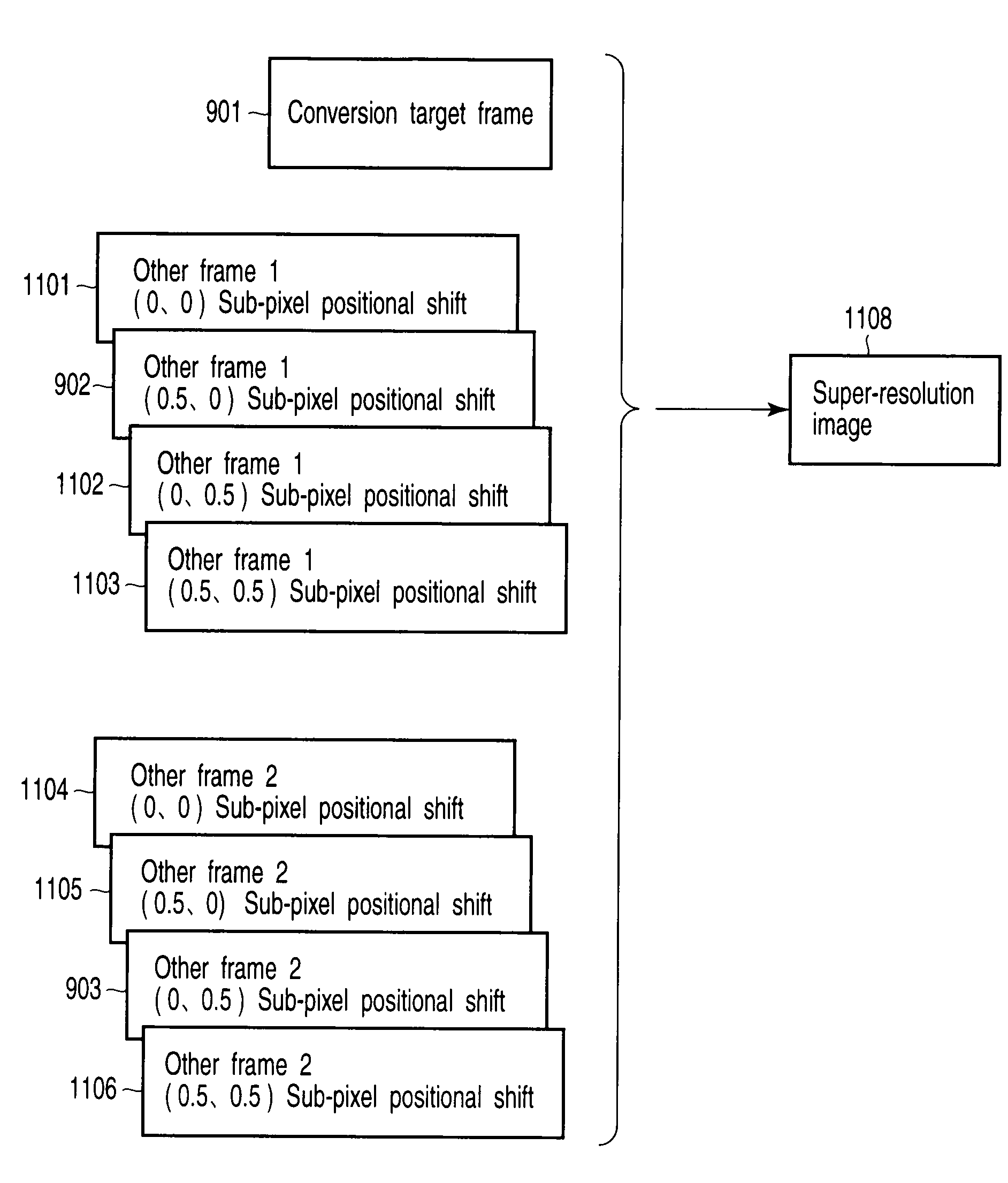
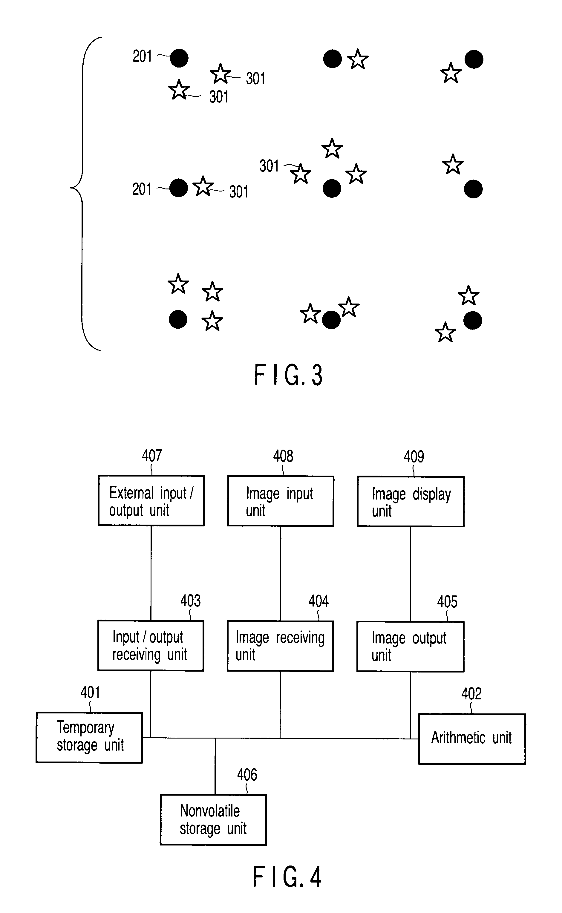
The invention is an image processing apparatus that can receive a series of frames of an image and process them to improve their quality. The apparatus includes a receiving unit to receive the frames, a setting unit to set one frame as a reference frame, and another frame as an other frame, a storage unit to store pre-calculated values, and an estimation unit to estimate the position of a corresponding point in the other frame based on the reference frame. This allows for easier selection of the most accurate value for each pixel in the image. Overall, the invention improves the accuracy and quality of images.

Problems solved by technology

However, if a registration error occurs, a high-resolution image degrades, as is known.
However, when a large registration error occurs at a part that does not match the model, no expected image is obtained by image reconstruction.
However, the sharpness does not largely improve when image reconstruction is performed.
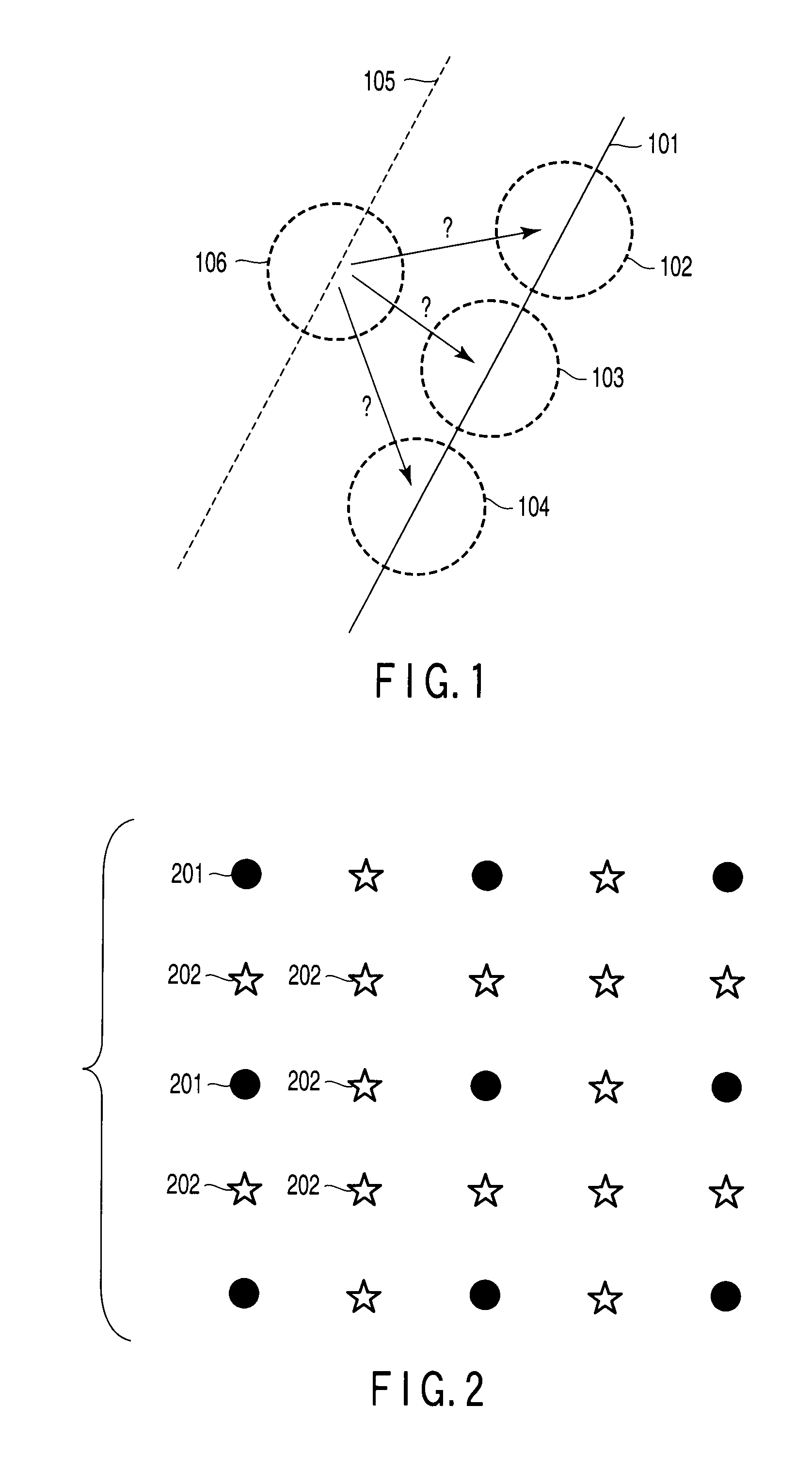
The inventors experimentally found that the reason why even local estimation cannot improve the sharpness is present in the aperture problem.
In estimating a motion from the first frame to the second frame, it is not possible to uniquely estimate the motion.
This problem is called an aperture problem.
The conventional method does not particularly execute arbitrary control.

Method used


Image

  • Image processing apparatus, method, and program
  • Image processing apparatus, method, and program
  • Image processing apparatus, method, and program

Examples


example 1

Block Matching SSD

[0106]A method will be examined, in which using an Lα error as a block error function, which is given by

Dα=∑(p,q)∈blockI(p,q,t)-I(p+Δp,q+Δq,t+Δt)α(whereαisarealnumber)(36)

or a robust error using a robust function ρ, which is given by

Dρ=∑(p,q)∈blockρ(I(p,q,t)-I(p+Δp,q+Δq,t+Δt))(37)

a position where the error value (the value of the Lα error or robust error) is minimized is obtained by block matching, and the shift of fractional accuracy is obtained by function fitting. Note that SSD and SAD correspond to Lα errors when α=2, and α=1, respectively. As the robust function ρ, for example, Huber's robust function given by

ρ(u)={u2u≤c2cu-c2u>c(38)

is used. A function obtained by setting an upper limit for, e.g., a SAD function, as is given by

ρ(u)={uu≤ccu>c(39)

is also usable. As the robust function ρ, a function described in C. V. Stewart, “Robust Parameter Estimation in Computer Vision”, SIAM Review, Vol. 41, No. 3, pp. 513-537 may be used. A multidimensional color spa...

example 2

Lucas-Kanade Method

[0131]The Lucas-Kanade method obtains a position to minimize the following expression, assuming two corresponding pixels (x,y,t) and (x+Δx,y+Δy,t+Δt) between frames. Note that weighting coefficients can be applied to errors at the pixels in a block to, e.g., place importance on the center. The presence / absence of weights does not largely change the calculation method (necessary weights can be applied), and a description thereof will be omitted below.

E=∑block(I(x+Δx,y+Δy,t+Δt)-I(x,y,t))2(42)

[0132]A linear Taylor expansion is applied to Expression (42). The expression to be minimized for the pixel (x,y,t) is a local energy function to be described below, in which u (=Δx / Δt) and v (=Δy / Δt) represent the horizontal and vertical speeds, respectively.

E=∑(∂I∂xu+∂I∂yv+∂I∂t)2(43)

where Σ is the sum for each pixel in the block. The expression can be minimized by calculating the least-square solution. This method has no bias to a specific subpixel positional shift and cannot ...

example 3

Energy Minimization

[0136]As a further method of obtaining a motion, a method of optimizing the consistency of individual motions and the balance of smoothness of motion vectors in the entire screen is known, like the Horn-Schunck method. This method (global motion optimization) can be formulated as a problem of (approximately) minimizing, e.g., the following energy function.

E=∑ρ1(∂I∂xu+∂I∂yv+∂I∂t)+λ∑ρ2((∂u∂x)2+(∂v∂x)2)(45)

This expression is similar to that of the Lucas-Kanade method. However, this energy function is given as one function not for each pixel but for the entire image. Each Σ represents the sum for all pixels of a frame as a motion calculation target, and λ represents a separately defined weight coefficient. Two values ρ can be either an Lα error or a robust error (they need not be the same function). Formulation by Horn et al. corresponds to use of SSD as the two values ρ. The former term evaluates the consistency of individual motions (whether the luminance error can ...


PUM


Abstract

An image processing apparatus includes a first receiving unit configured to receive a plurality of frames of an image containing pixel values, a first setting unit configured to set one of the frames as a reference frame, a second setting unit configured to set, of the frames received by the first receiving unit, one frame other than the reference frame as an other frame, a first storage unit configured to store at least one subpixel shift value that is a preset fractional value, and an estimation unit configured to estimate a fractional part of a position of a corresponding point corresponding to a pixel of the other frame to readily select a value closer to the subpixel shift value.

Description

CROSS-REFERENCE TO RELATED APPLICATIONS[0001]This application is based upon and claims the benefit of priority from prior Japanese Patent Application No. 2007-250181, filed Sep. 26, 2007, the entire contents of which are incorporated herein by reference.BACKGROUND OF THE INVENTION[0002]1. Field of the Invention[0003]The present invention relates to an image processing apparatus, method, and program for a motion vector estimation method used to, e.g., obtain a sharp image at a higher resolution from an input image.[0004]2. Description of the Related Art[0005]To maintain the sharpness of an image to be converted into a higher resolution, a method is used which estimates the pixel values of sampling points of non-integer coordinates by searching for corresponding points of a plurality of frames, and obtains the image at the output resolution by integrating the pieces of information. This technique is named super-resolution (e.g., S. C. Park et al., “Super-Resolution Image Reconstructio...

Claims


Application Information

Patent Timeline
Patent Type & Authority Applications(United States)
IPC IPC(8): H04N5/14
CPCG06T3/4069H04N5/144H04N7/014H04N7/0125H04N5/205
Inventor TAKESHIMA, HIDENORIKANEKO, TOSHIMITSUIDA, TAKASHI
Owner KK TOSHIBA
Learn More