Switching device
- Summary
- Abstract
- Description
- Claims
- Application Information
AI Technical Summary
Benefits of technology
Problems solved by technology
Method used
Image
Examples
first embodiment
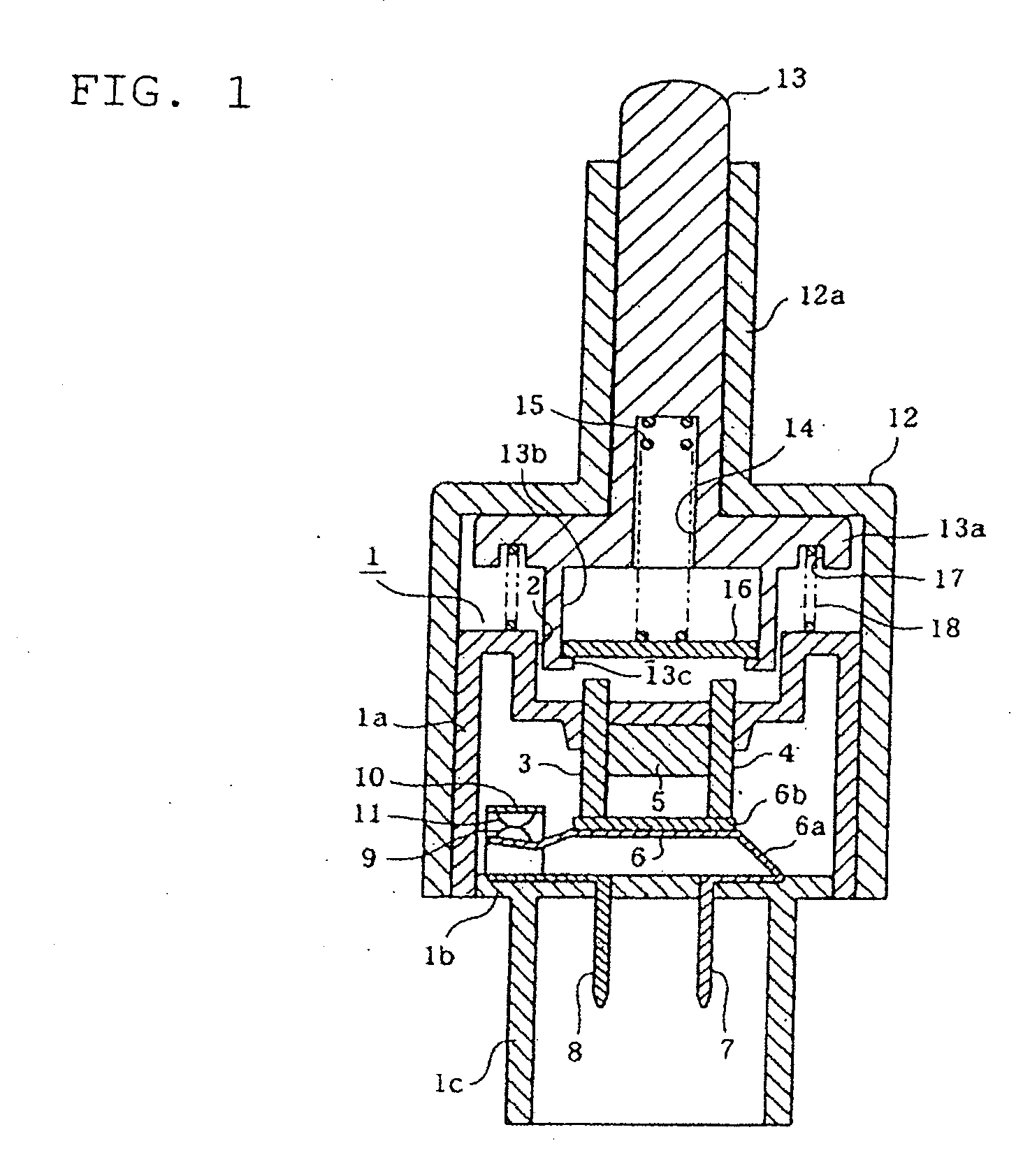
[0015]The present invention is applied to a stop lamp switch for a vehicle, and its first embodiment (a first mode of practice of the invention) will be described hereunder by reference to FIGS. 1 through 3.
[0016]First, FIG. 1 shows the configuration of an over all vehicle stop lamp switch, and the stop lamp is primarily made up of a sealing case 1. The sealing case 1 includes a case main section 1a and a case bottom plate 1b. The case main section 1a wholly assumes the shape of a square box, wherein an upper surface portion of the main section is closed and wherein a bottom of the main section is opened.
[0017]A recess 2 is formed in the center of the upper surface portion of the case main body section 1a, and yokes 3 and 4 are provided so as to penetrate into the case main body section 1a from the bottom of the recess 2. The yokes 3 and 4 are formed from a magnetic material, such as iron; namely, possess a magnetic property. The yokes are provided as inserts at the time of molding ...
second embodiment
[0040]In a second embodiment shown in FIGS. 4 through 6, a sealing case 21 is first made up of an essentially-dome-shaped case main body section 21a and a case bottom plate 21b in place of the sealing case 1 of the first embodiment.
[0041]As in the case with the yokes 3 and 4 in the case main body section 1a of the first embodiment, yokes 22 and 23 are provided in an upper portion of the case main body section 21a so as to protrude upward of the case main body section 1a much greater than the yokes 3 and 4. The yokes 22 and 23 take the place of the yokes 3 and 4 of the first embodiment; are made of a magnetic material, such as iron; and possess magnetism.
[0042]In the case main body section 21a, the magnet 5 is sandwiched between the yokes 22 and 23 in a contacting manner, and a movable contact 24 is disposed at a position immediately below the yokes 22 and 23. The movable contact 24 takes the place of the movable contact 6 of the first embodiment, and is made up of a contact main pla...
third embodiment
[0059]In a third embodiment shown in FIG. 7, sections 41 and 42 adjoining exteriors of the respective yokes 3 and 4 of the case main body section 1a of the first embodiment are formed so as to extend vertically, thereby making a section 43 adjoining interiors of the respective yokes 3 and 4 extend upwardly.
[0060]As opposed to the yokes 3, 4 and the magnetic shunt element 16 that are made of metal, the case main body section 1a is formed from resin molded by inserting the yokes 3 and 4; in particular, a synthetic resin. Since the case main body section 1a is held in close contact with the yokes 3 and 4, the extending sections 41 to 43 of the case main body section 1a are integrated, as members made of a resin, closely with the yokes 3 and 4. Moreover, the resin is a sound proofing material. Consequently, the extending sections 41 to 43 are integrated, as a soundproofing material made of a resin, closely with the yokes 3 and 4.
[0061]Further, upwardly-stretching portions of the extendi...
PUM
 Abstract
Description
Claims
Application Information
 - R&D
- Intellectual Property
- Life Sciences
- Materials
- Tech Scout
- Unparalleled Data Quality
- Higher Quality Content
- 60% Fewer Hallucinations
Browse by: Latest US Patents, China's latest patents, Technical Efficacy Thesaurus, Application Domain, Technology Topic, Popular Technical Reports.
© 2025 PatSnap. All rights reserved.Legal|Privacy policy|Modern Slavery Act Transparency Statement|Sitemap|About US| Contact US: help@patsnap.com


