Railroad switching indicator mechanism

Inactive Publication Date: 2009-03-19
J RAIL COMPONENTS & MFG INC
View PDF38 Cites 19 Cited by
  • Summary
  • Abstract
  • Description
  • Claims
  • Application Information

AI Technical Summary

Benefits of technology

[0016]It is therefore an object of the present invention to provide a railroad switching indicator mechanism which is extremely reliable and assures that points in a switching apparatus have completely traveled from one position to another position to effect of switching of rails for a railroad train.
[0017]Another object of the present invention is to provide a railroad switching indicator mechanism which is durable and reliable.
[0019]Its another object of the present invention is to provide a railroad switching indicator mechanism which may be retrofitted to railroad switching apparatus.

Problems solved by technology

If such positioning does not take place within strict tolerances (¼″ or greater), this would indicate a switching obstruction which could result in a train being derailed at the switching apparatus.
However, it has been found that prior detector mechanism are subject to mechanical wear and, at times, break or provide a false signal as to the switching position of the points.
Electronic sensors have also been devised but have not proven to be durable enough to properly operate over long periods of time.

Method used


Image

  • Railroad switching indicator mechanism
  • Railroad switching indicator mechanism
  • Railroad switching indicator mechanism

Examples


Embodiment Construction

[0029]Various aspects of the present invention will evolve from the following detailed description of the preferred embodiments thereof which should be referenced to the prior described drawings.

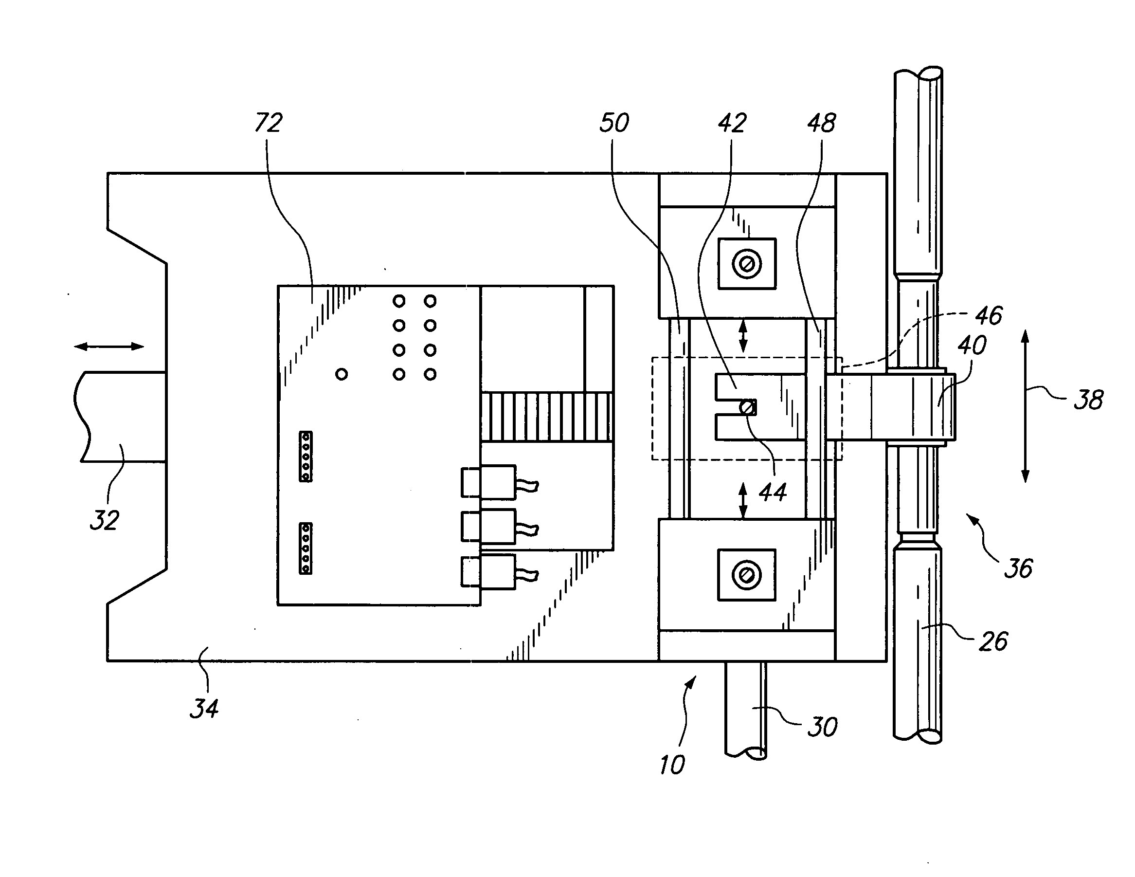
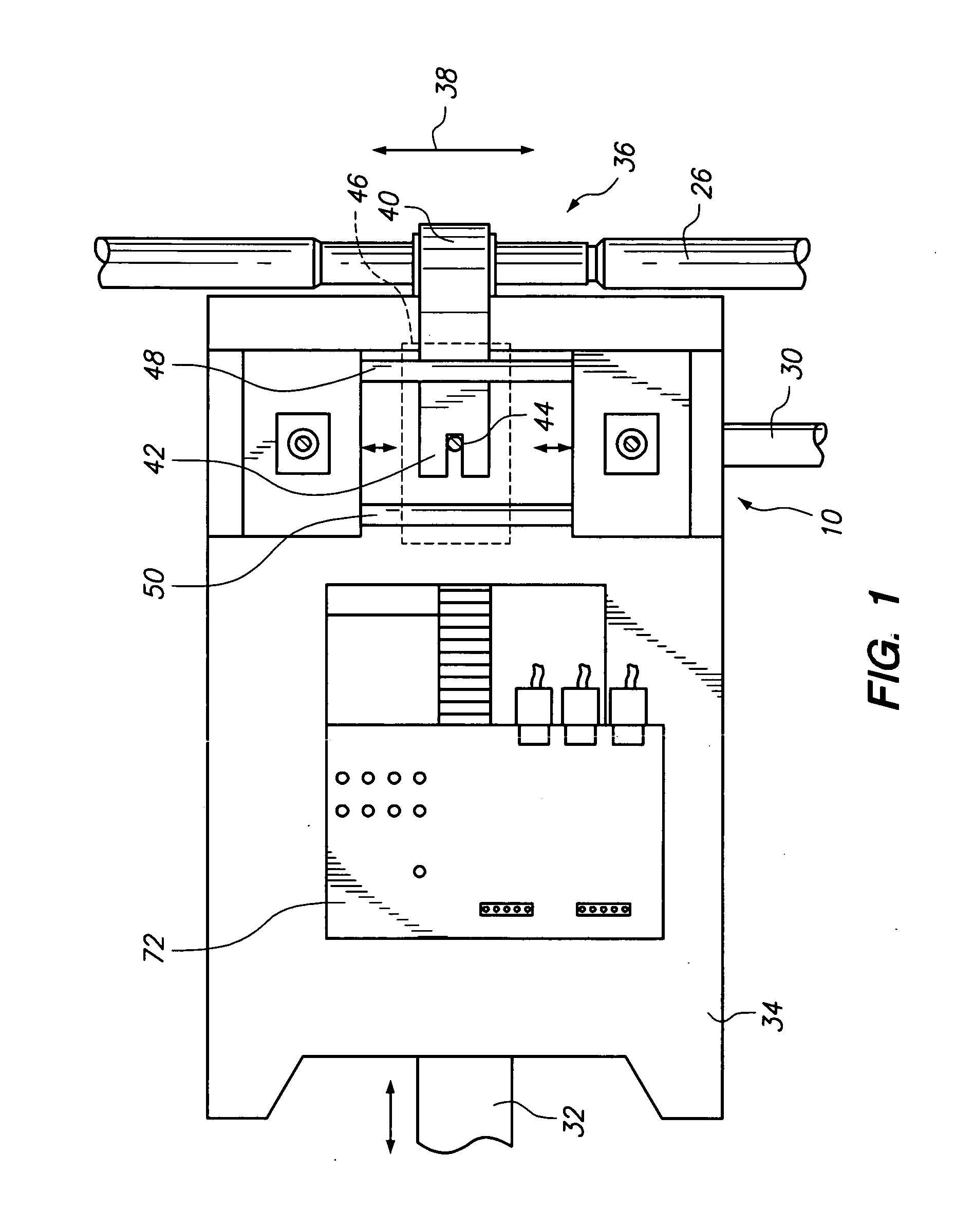
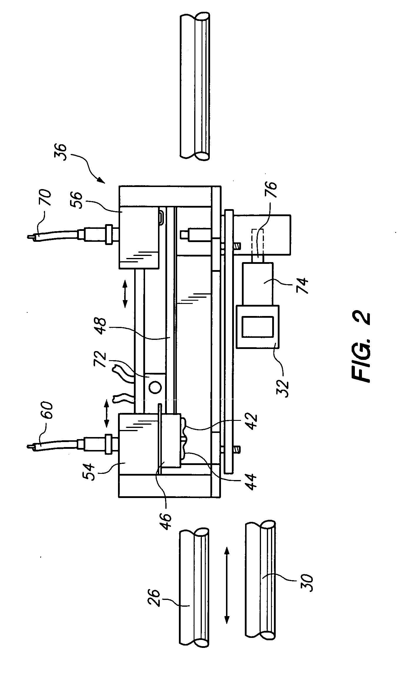
[0030]Mechanism 10, FIG. 1, is employed with a railroad switching apparatus 12, well known in the art. With reference to FIG. 6, it may be observed that a plurality of cross-ties 14 support fixed rails 16 and 18 on a bed or surface 20. Points or blades 22 and 24 are moved between fixed rails 16 and 18 by an electrical motor or manually through a mechanical linkage, not shown. An internal point detector bar / or indicator rod 26 moves with points 22 and 24 according to directional arrow 28. Likewise, internal point locking rod 30 also moves with points 22 and 24 and interacts with a locking bar 32 through a series of notches found on internal point locking rod 30, Such interaction is known and prior described in U.S. Pat. No. 2,348,707, as well as in other prior art documents. In any case, inte...


PUM


Abstract

A railroad switching indicator apparatus for use with a point detector bar, and a point locking rod which cooperatively locks with a locking bar. First and second point detector bar receptors generate first and second signals indicating the first and second terminal movements of the point detector bar. At the same time, a point lock rod receptor generates another signal indicating the locking of the locking bar with the point locking rod.

Description

BACKGROUND OF THE INVENTION[0001]The present invention relates to a novel and useful railroad switching indicator mechanism for use with an internal point detector bar, and an internal point lock rod which cooperates with a locking bar.[0002]It is often necessary to switch a railroad track to allow a train to travel therefrom to either of two tracks which split away from the first track. To achieve this result, switch mechanisms have been deployed for many years utilizing moveable rails. The moveable rails are normally referred to as points or blades, since such rails narrow to an edge at one end thereof. Known mechanisms, in the form of switching apparatuses, include an internal point lock rod which cooperates or interacts with a locking bar to hold the points against the fixed rails. In addition, an internal point detector bar is employed in order to assure that the movement of the points has taken place completely such that the points are positioned closely to the fixed rail. If ...

Claims


Application Information

Patent Timeline
IPC IPC(8): B61L5/10
CPCB61L5/107
Inventor ARNOLD, JIM
Owner J RAIL COMPONENTS & MFG INC
Why Eureka
Try Eureka