
Splitting Apparatus and Manipulating Apparatus for Optical Waveguides

a technology of optical waveguides and manipulating apparatuses, applied in the field of optical devices, can solve the problems of reducing the number of parts required, reducing the flexibility of the region of the first bushing region of the bundled core, and causing a lot of work

Inactive Publication Date: 2009-03-12
CCS TECH INC
View PDF23 Cites 17 Cited by
  • Summary
  • Abstract
  • Description
  • Claims
  • Application Information

AI Technical Summary

Benefits of technology

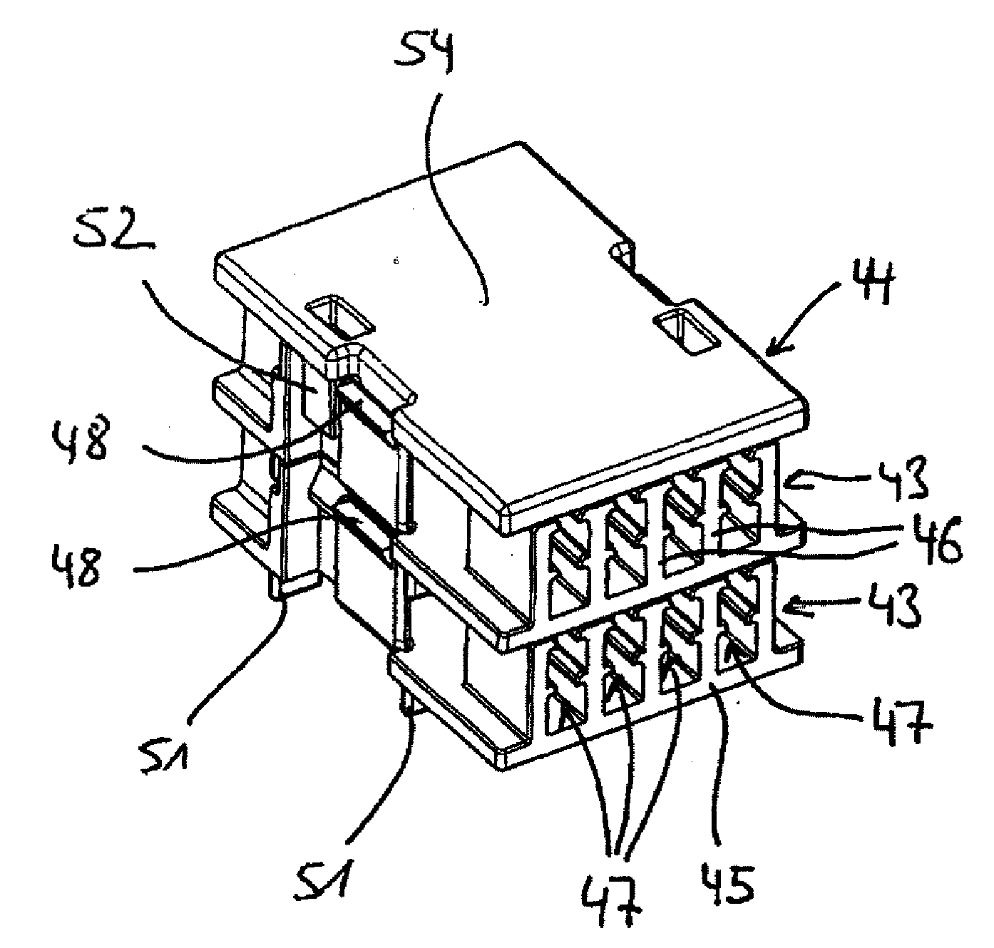
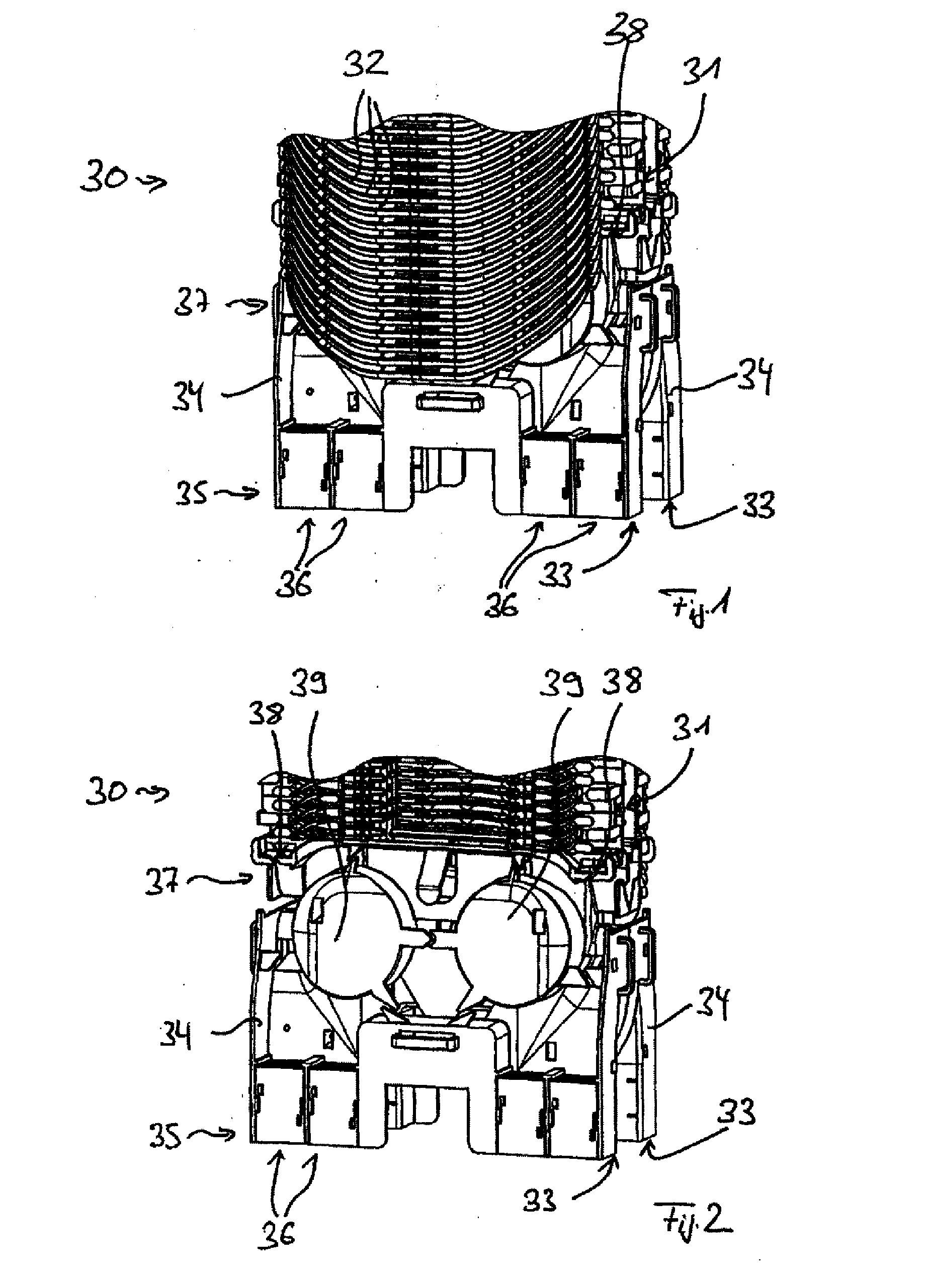
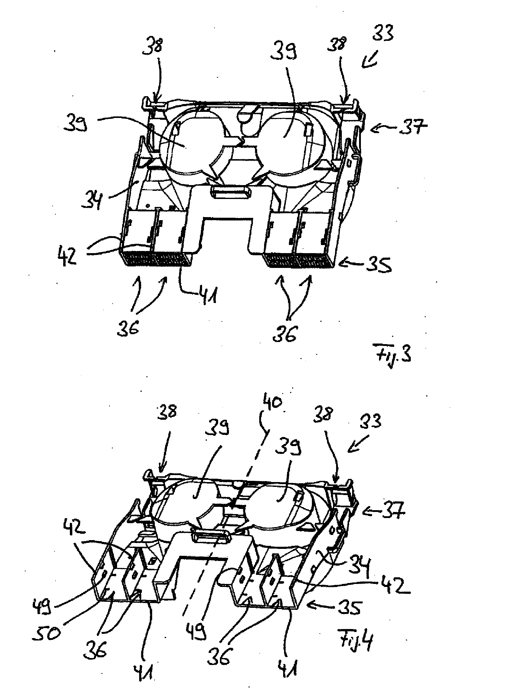
[0010]At least one bundled core guide device can be inserted into each bushing region for bundled cores. The bundled core guide device can be provided in advance with bundled cores outside the region of the splitting apparatus. Such a bundled core guide device which has been provided in advance with bundled cores can then be positioned in the respective bushing region of the splitting apparatus. As a result, the manipulation and laying of bundled cores is simplified. Furthermore, bundled core guide devices with different designs can be arranged in the bushing regions of the splitting apparatus, as a result of which the flexibility thereof is increased. Furthermore, the number of parts required is reduced, which likewise simplifies manipulation of the splitting apparatus in comparison with the splitting apparatus known from the prior art.

Problems solved by technology

This is complex and laborious.
Furthermore, the splitting apparatus for optical waveguides known from WO 2004 / 051337 A1 has restricted flexibility in the region of the first bushing regions for the bundled cores since all of the bundled cores need to be fixed in a first bushing region in the same laborious manner.

Method used


Image

  • Splitting Apparatus and Manipulating Apparatus for Optical Waveguides
  • Splitting Apparatus and Manipulating Apparatus for Optical Waveguides
  • Splitting Apparatus and Manipulating Apparatus for Optical Waveguides

Examples


Embodiment Construction

[0009]The embodiments disclosed in the detailed description include a splitting apparatus and manipulating apparatus for optical waveguides. The splitting apparatus has a bottom plate, a first side and a second side. At least one bundled core guide device, which is used for guiding and / or restraining a plurality of bundled cores, can be inserted into a first bushing region of a splitting apparatus on the first side in such a way that the bundled core guide device latches detachably with ribs and / or the bottom plate of the respective first bushing region. A second bushing region can receive the optical waveguides on the second side, wherein the optical waveguides are individual or loose from the bundled cores.

[0010]At least one bundled core guide device can be inserted into each bushing region for bundled cores. The bundled core guide device can be provided in advance with bundled cores outside the region of the splitting apparatus. Such a bundled core guide device which has been pro...


PUM


Abstract

A splitting apparatus and manipulating apparatus for optical waveguides is disclosed. The splitting apparatus has a bottom plate, a first side and a second side. At least one bundled core guide device, which is used for guiding and / or restraining a plurality of bundled cores, can be inserted into a first bushing region of a splitting apparatus on the first side in such a way that the bundled core guide device latches detachably with ribs and / or the bottom plate of the respective first bushing region. A second bushing region can receive the optical waveguides on the second side, wherein the optical waveguides are individual or loose from the bundled cores.

Description

CROSS-REFERENCE TO RELATED APPLICATIONS[0001]This application is a continuation of International Application No. PCT / EP2007 / 002780, filed Mar. 29, 2007, which claims priority to German Application No. DE202006006016.2, filed Apr. 11, 2006, both applications being incorporated herein by reference.BACKGROUND[0002]1. Technical Field[0003]The invention relates to optical devices, and more particularly to a splitting apparatus for optical waveguides, and further to a manipulating apparatus for optical waveguides.[0004]2. Technical Background[0005]WO 2004 / 051337 A1 has disclosed a cable sleeve for laying optical waveguides guided in fiberoptic cables which comprises, in a region below splicing cassettes, two splitting apparatuses for optical waveguides which are positioned back to back. Each of the splitting apparatuses has a basic body, which has, on a first side, a plurality of first bushing regions for bundled cores of optical waveguides and, on a second side, second bushing regions fo...

Claims


Application Information

Patent Timeline
IPC IPC(8): G02B6/00
CPCG02B6/4471G02B6/4454
Inventor KNORR, JENSMULLER, THORSTENSYPLACZ, ROMAN ARNOLD THEODORKLUWE, WOLFLAPP, OLIVERMULLER, MICHAELTHIBAULT, SIMON
Owner CCS TECH INC
Learn More