
Hinge Structure

a technology of hinge structure and hinge, which is applied in the direction of wing accessories, instruments, portable computers, etc., can solve the problems of increased assembly complexity, unusable design, and unfriendly design, and achieve the effect of small force and improved user-unfriendly design

Active Publication Date: 2009-03-12
JARLLYTEC CO LTD
View PDF10 Cites 5 Cited by
  • Summary
  • Abstract
  • Description
  • Claims
  • Application Information

AI Technical Summary

Benefits of technology

[0005]In view of the foregoing shortcomings of the prior art, the inventor of the present invention based on years of experience in the related industry hopes to improve the user-unfriendly design of “easy opening and firm closing” for conventional auto-locking hinge structure. The aim is to include a variable torque mechanism to a hinge structure and thereby when the hinge structure according is being flipped open, the torque required for “firm opening and easy closing” is dispersed and thus a small force is sufficient to flip open the cover without lifting up the main body. After numerous experiments and tests, a hinge structure according to the present invention has been achieved.
[0012]Still yet another object of the present invention is to provide a hinge structure, wherein a stop rim is protrudingly disposed at the wall of one end of the tube spring and a fan-shape limit stop is protrudingly disposed at the rear end of the shaft, such that the two ends of the stop rim and the limit stop can limit the angle of opening and closing movement.

Problems solved by technology

However for this type of automatic locking mechanism, the rotating shaft structure with automatic locking mechanism has to be provided with corresponding holes and locking elements, leading to an increase in the complexity for assembly and the manufacturing cost.
It is not a user-friendly design because a rather large force has to be exerted to flip open the cover body.
As a result, the flipping opening motion usually requires the user to press down the main body with the other hand; otherwise, the main body will be lift upward along with the cover body, thereby causing inconvenience.

Method used


Image

  • Hinge Structure
  • Hinge Structure
  • Hinge Structure

Examples


Embodiment Construction

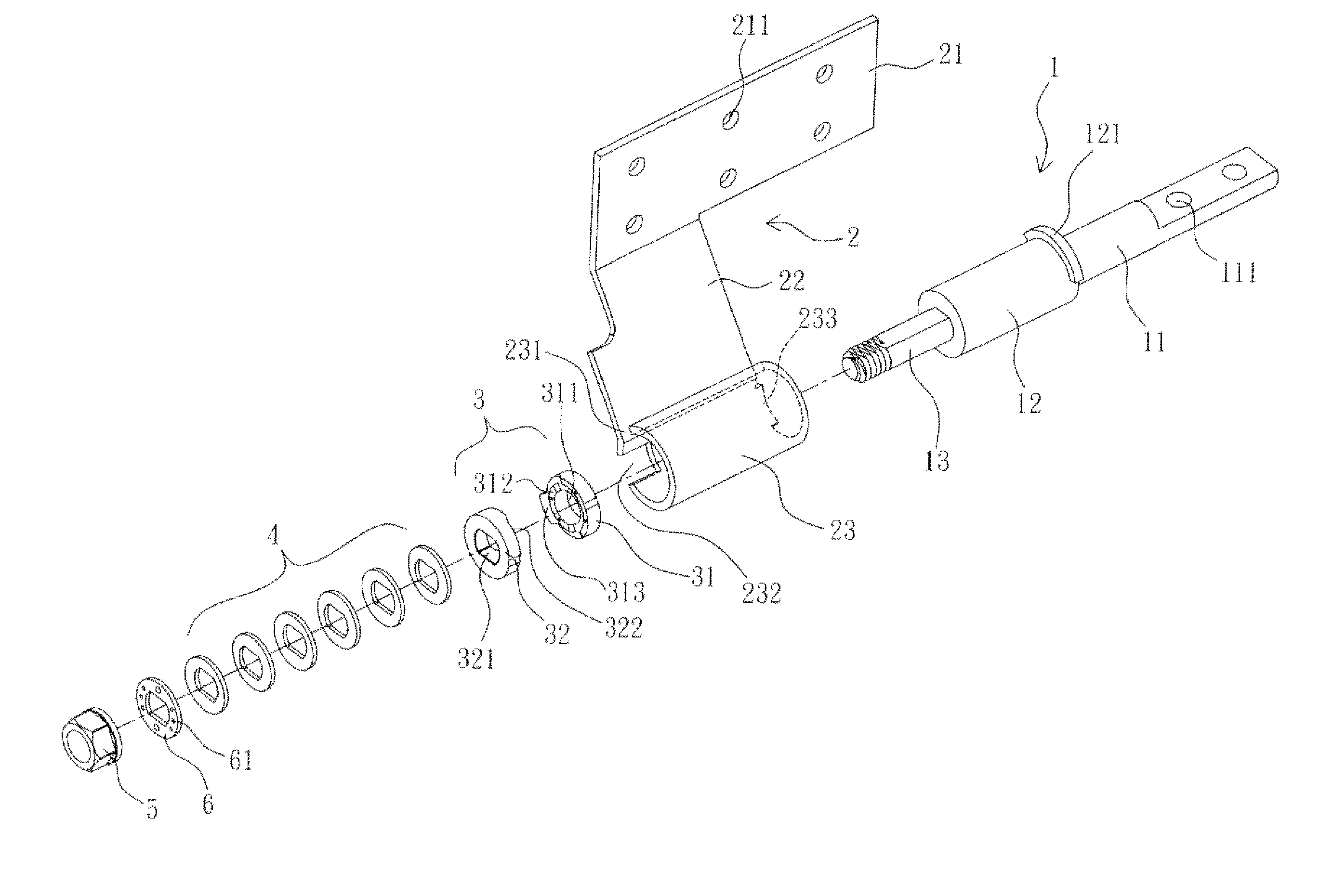
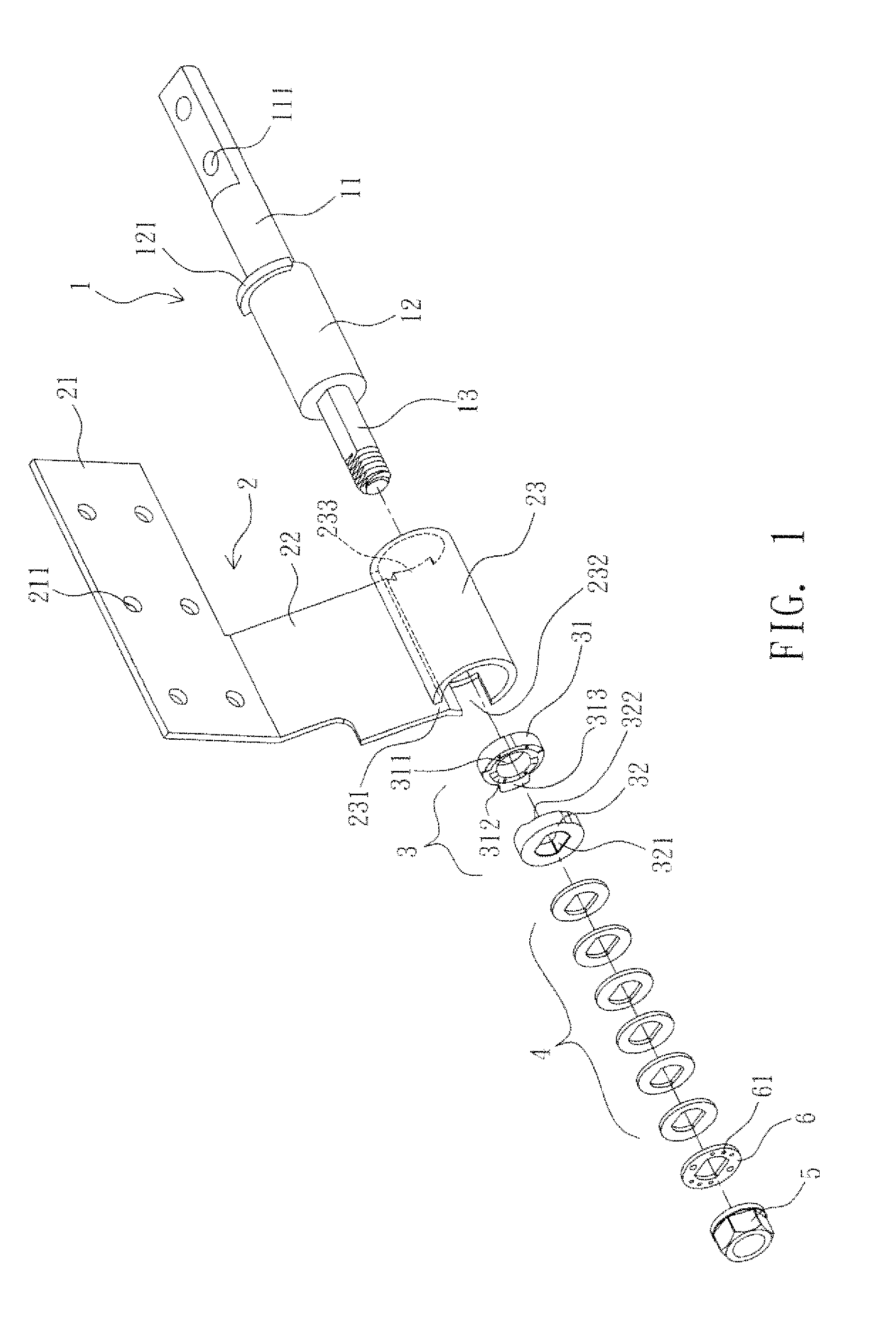
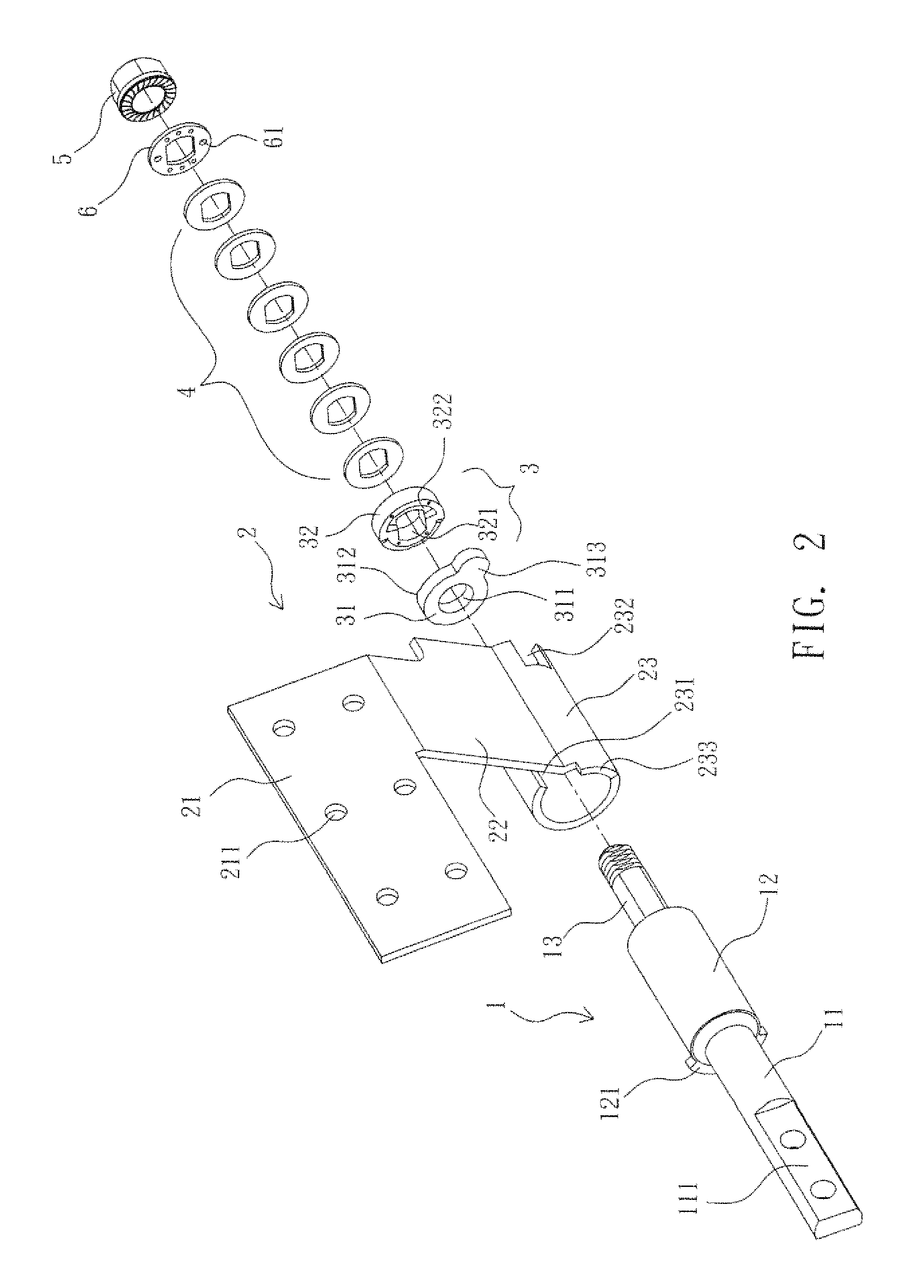
[0019]With reference to FIGS. 1 to 4, a hinge structure according to the present invention comprises a pivot 1, a main frame 2, a cam member 3, and at least a resilient member 4.

[0020]The pivot 1 is a multi-step shaft disposed with a linking portion 11 formed to have at least a linking hole 111 to be connected with an object, for example but not limited to the main body of a notebook computer. The linking portion 11 when implemented can be a mill-face prism or a polyhedron so as to be directly inserted into the main body. The pivot 1 according to the present invention is characterized by that it is axially disposed with a circular shaft 12 which is extending to form a smaller axle 13 from its center of the front end.

[0021]The main frame 2 is a frame formed by bending, having on its one side a connection portion 21 which is formed to have at least a connection hole 211 to be connected with an object, for example but not limited to the main body of a notebook computer. The connection ...


PUM


Abstract

The present invention discloses a hinge structure comprising a pivot having a linking portion disposed with a circular axle axially and a smaller axle extending from the center of the front end of the shaft; a main frame having a connection portion which is formed axially to have a bush-like tube spring below for the insertion of the shaft, the tube spring being positioned to have a gap with the connection portion and one end of the wall of the tube spring being formed to have an notch; a cam member having a rotation part and fixed part between which is disposed with concurrent protruded and to indented portions and which are installed inside the tube spring for the insertion of the axle, the rotation par being axially disposed with a protruded tenon which is connected with the notch of the tube spring, and the fixed part being secured with the axle, and at least a resilient member insertingly connected with the axle and secured with the connection segment of the axle by an end enclosure, which presses and constrains the aforementioned parts.

Description

FIELD OF THE INVENTION[0001]The present invention relates to a hinge structure and in particular to a variable-torque hinge structure with auto-locking and easy opening-firm closing functions.BACKGROUND OF THE INVENTION[0002]Consumer electronics with flip covers, such as portable computer, electronic dictionary, portable audio / video player, flip mobile phone, generally have a main body on the bottom, which is pivotally connected with the cover to body on the top, such that the cover body may swing open or close with respect to the main body. Consequently, the rotating axle is key to the quality of the products described above.[0003]To prevent the main body and the cover of the 3C electronic products described above from swinging open arbitrarily, at least a sliding or pressing switch is provided at the respective limit of the movement angle such that the switch may be used to fold them together to close down during swinging close. However for this type of automatic locking mechanism...

Claims


Application Information

Patent Timeline
Patent Type & Authority Applications(United States)
IPC IPC(8): E05D11/10
CPCE05D11/1078E05Y2900/606G06F1/1616G06F1/1681Y10T16/5387Y10T16/54038Y10T16/540345Y10T16/540255Y10T16/5402E05Y2999/00
Inventor CHANG, JUI-HUNG
Owner JARLLYTEC CO LTD
Learn More