
Tibial preparation apparatus and method

a technology for tibia and apparatus, applied in the field of tibial preparation apparatus and method, can solve the problem of reducing the manipulative clearance available to the surgeon

Inactive Publication Date: 2009-03-05
BIOMET MFG CORP
View PDF26 Cites 32 Cited by
  • Summary
  • Abstract
  • Description
  • Claims
  • Application Information

AI Technical Summary

Problems solved by technology

The prior art handle may obscure the view of the trial trays or guides and make alignment evaluation cumbersome, and generally reduces the manipulative clearance available to the surgeon.

Method used


Image

  • Tibial preparation apparatus and method
  • Tibial preparation apparatus and method

Examples


Embodiment Construction

[0013]The following description of the embodiments is merely exemplary in nature and is in no way intended to limit the invention, its application, or uses.

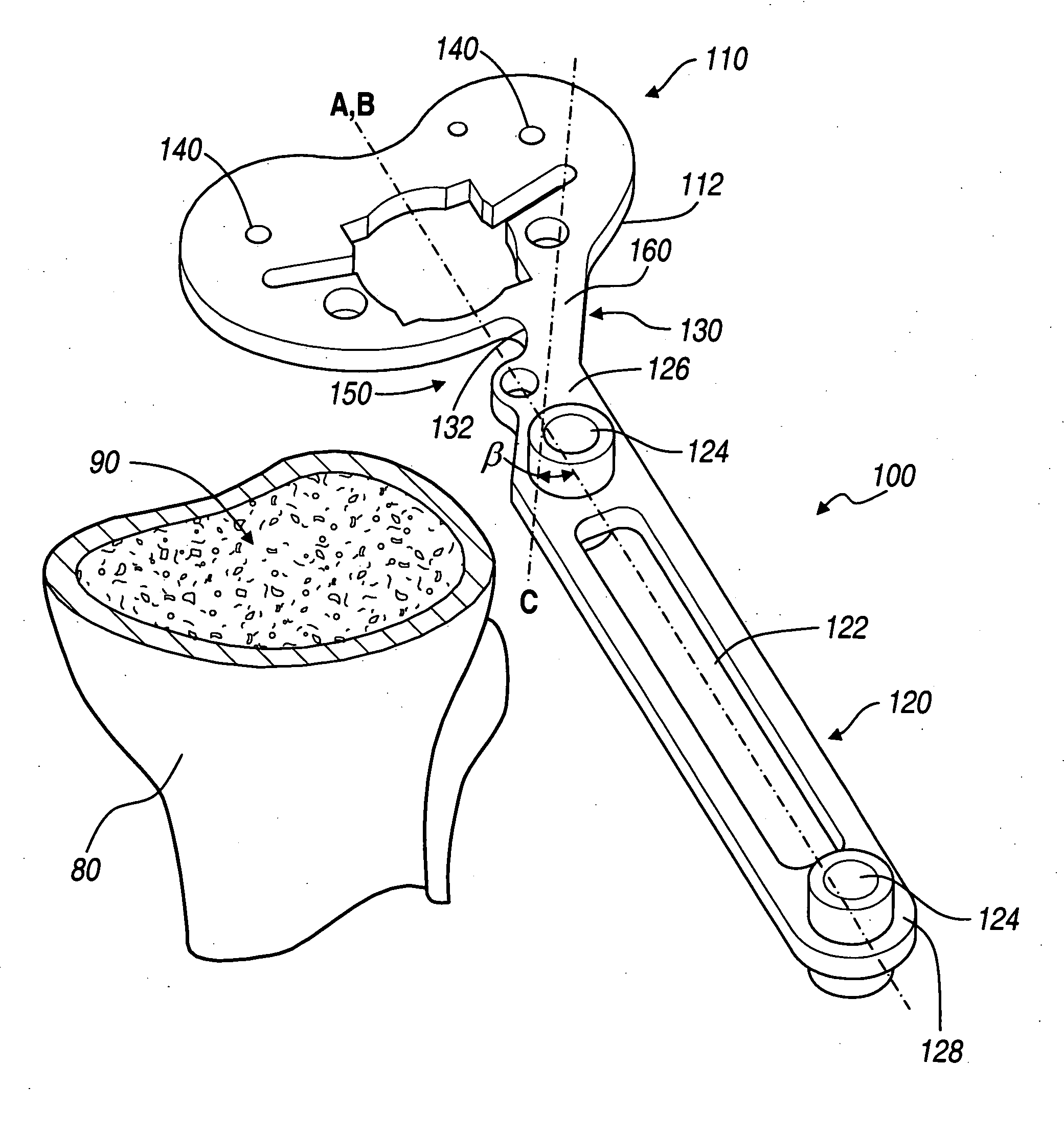
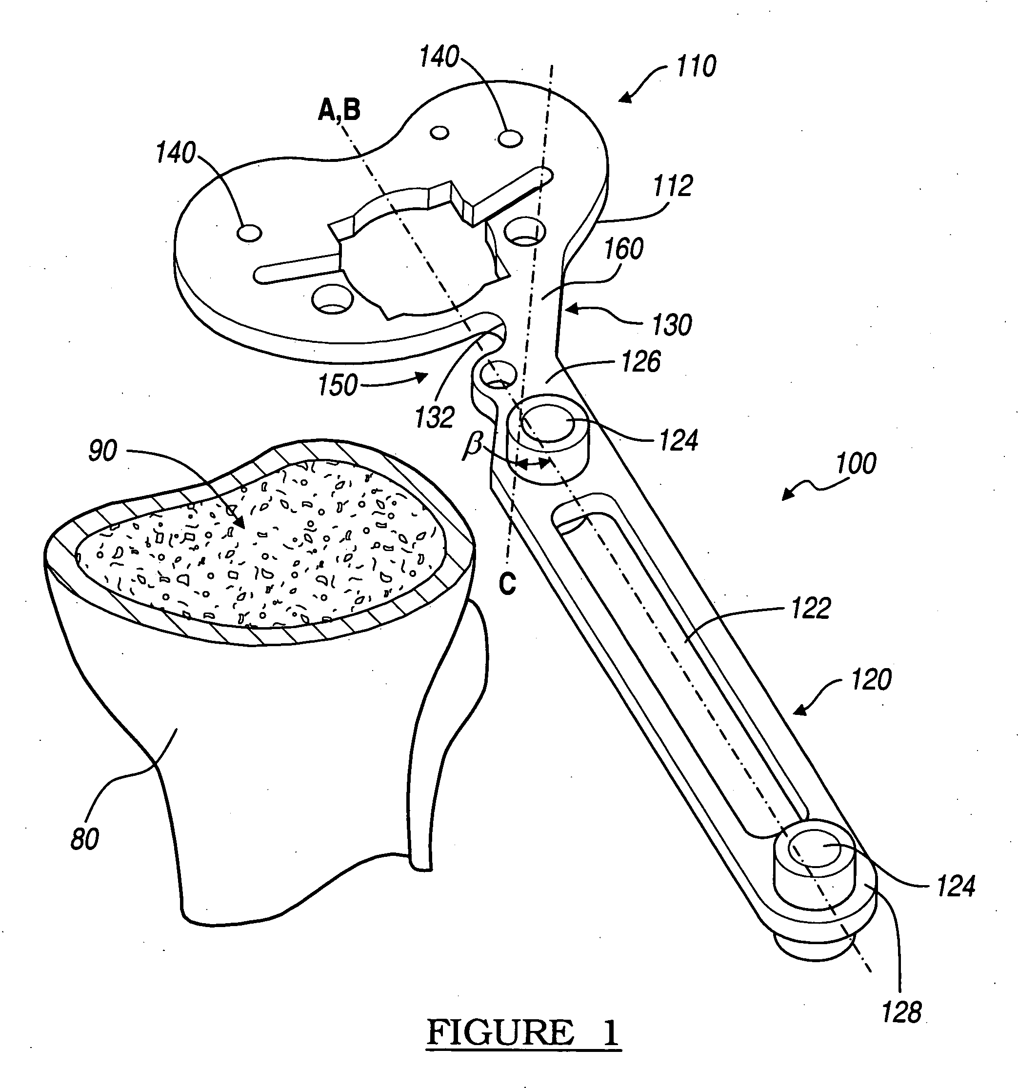
[0014]FIG. 1 illustrates an embodiment for an apparatus 100 used to prepare a tibial surface 90 for knee surgery. The apparatus 100 is shown in the exemplary environment of a right knee tibial bone 80. The apparatus 100 includes a tibial base 110, a handle 120, and a link 130. The tibial base 110 can be a tibial template, a trial tibial tray or plate, a punching, reaming, cutting, or alignment guide or jig, or any other component that may be placed on the tibial surface 90 in preparation for knee replacement surgery. The tibial base 110 may be reversible in some embodiments, such as, for example when the tibial base 110 is a tibial template. The tibial base has a periphery 112 and a center axis “A”, which is generally, but not necessarily, an axis of symmetry of the tibial base 110. The tibial base 110 may be temporarily secured ...


PUM


Abstract

An apparatus and method for preparing a tibia for knee surgery. The apparatus includes a tibial base having a center axis, and a handle coupled to the base at an anterior base location that is offset relative to the center axis.

Description

FIELD OF THE INVENTION[0001]The present invention relates to an apparatus and method for tibial preparation.BACKGROUND OF THE INVENTION[0002]During knee replacement surgery the tibial surface may be prepared for implantation of a tibial component of a knee implant. Several preparation instruments may be used to assist the surgeon in this procedure. A surgeon generally uses, for example, a tibial template and / or trial tibial tray to determine the tibial implant size, as well as various cutting, punching or reaming guides to make the appropriate cuts or reamed surfaces in the bone, and to ensure a proper alignment prior to implanting the tibial component.[0003]The tibial preparation procedure typically starts with making an initial tibial plateau cut on the proximal tibia of the knee joint. Using a tibial template, the size of the trial tray is then selected and placed over the resected surface of the tibia. After trial reduction, the trial tray is removed and a punch guide is placed ...

Claims


Application Information

Patent Timeline
IPC IPC(8): A61B17/17
CPCA61B17/1764
Inventor SCOTT, JAMES W.METZGER, ROBERT G.
Owner BIOMET MFG CORP
Learn More