
Remotely controlled traffic beacon

a remote control and traffic beacon technology, applied in the field of traffic beacons, can solve the problems of large power consumption of the circuitry involved in these technologies, and neither of these technologies contains the ability to transmit operational feedback information to the user, so as to reduce installation costs, increase the geographic range of installation, and reduce electrical energy.

Inactive Publication Date: 2009-02-26
J S FOSTER
View PDF23 Cites 8 Cited by
  • Summary
  • Abstract
  • Description
  • Claims
  • Application Information

AI Technical Summary

Benefits of technology

[0007]The invention possesses advantages over existing beacons. The invention utilizes a cellular telephone modem and public cellular telephone networks for communications between the user and the beacon. Thus it enables the beacon to be installed in wider geographic regions without the installation of additional communications infrastructure. The invention therefore increases the geographic range of installation and reduces installation cost. In addition, because cellular-telephone modems use relatively less electrical energy than conventional communication system hardware, the communications system can remain active 24-hours a day, thus allowing for immediate communications and activation / deactivation of the solar-powered traffic beacon.
[0008]A practical example of the benefits possessed by the invention resides in the ability to install the beacons, without modification and without additional communications infrastructure, anywhere in the world that can be reached by a cellular telephone signal. The present invention, given its use of a cellular telephone modem, is suited to take advantage of the wide geographic spread of public cellular telephone networks. Furthermore, the low power consumption requirement of a cellular telephone modem allows the communications system to be active 24-hours a day.

Problems solved by technology

Generally speaking, conventional devices make use of either public pager networks which are limited in range to major cities, or private radio broadcasts which necessitate the building of private radio towers positioned to transmit radio signals to the beacons.
Within the beacon, the circuitry involved in these technologies has relatively large power consumption, thus necessitating either a larger than desired solar power plant or only an intermittent activation cycle.
Furthermore, neither of these technologies contains the ability to transmit operational feedback information to the user over a long distance.

Method used


Image

  • Remotely controlled traffic beacon
  • Remotely controlled traffic beacon
  • Remotely controlled traffic beacon

Examples


Embodiment Construction

[0058]The invention provides an improved remotely controlled solar-powered traffic beacon. Remote control is provided by a communications system that utilizes a cellular telephone modem, positioned inside the beacon, to receive a schedule of activation / deactivation or alternatively to receive immediate on / off commands. Furthermore, the communications system allows for the transmission of operational feedback data from the solar-powered traffic beacon to the user.

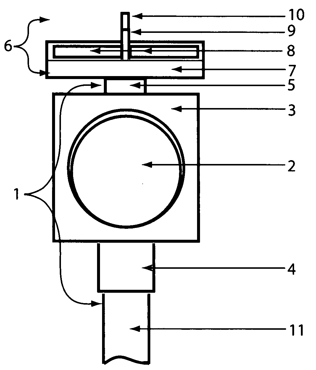
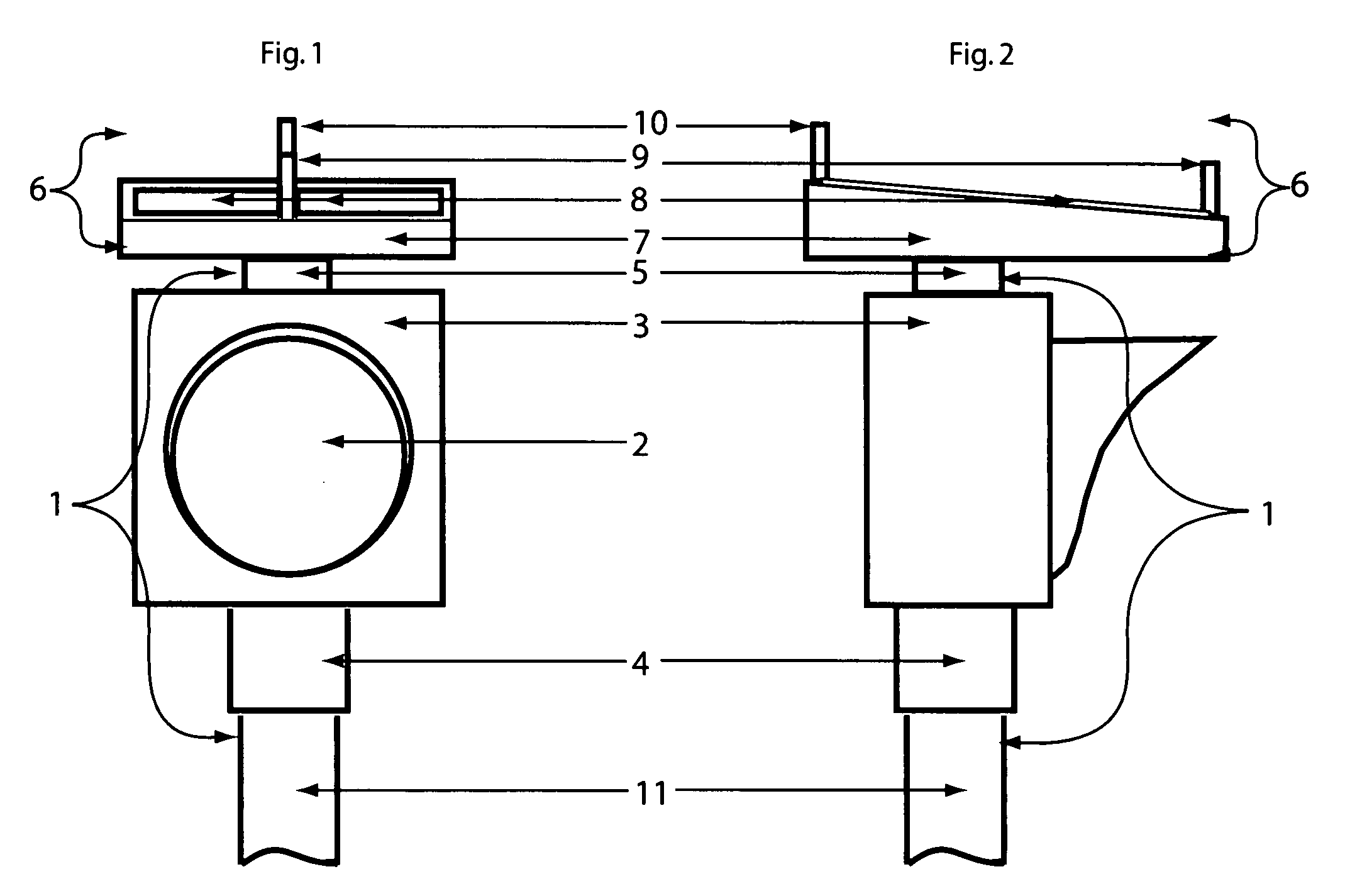
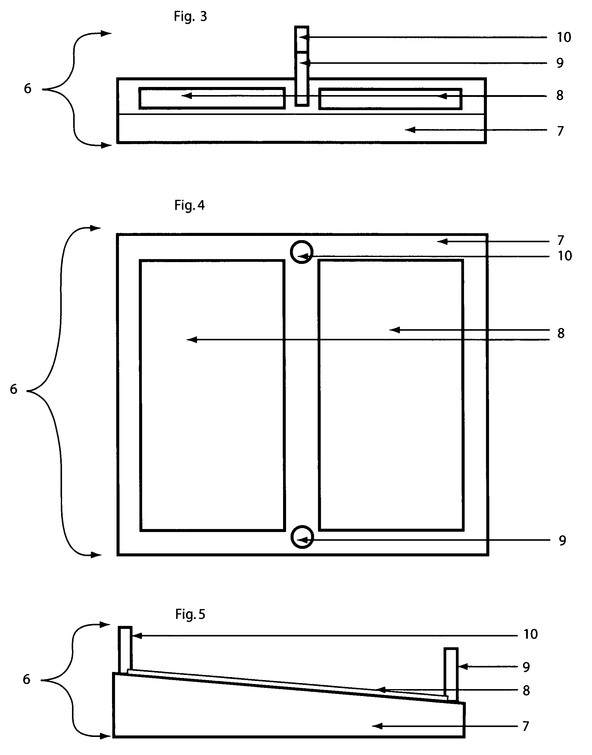
[0059]FIGS. 1 and 2 and 4 illustrate the remotely controlled solar-powered traffic beacon according to the preferred embodiment. The principal components of the beacon are the signal light sub-assembly 1 and power plant sub-assembly 6.

[0060]As visible in FIGS. 1 and 2, the signal light sub-assembly 1, includes at least one lamp 2 mounted within a lamp head with visor 3 in a conventional manner, mounting collar 4 and connection collar 5, which are deployed on pole 11 by means of set-screws (not shown).

[0061]The power plant su...


PUM


Abstract

The invention provides an improved remotely controlled, solar-powered traffic beacon. Remote control is provided by a communications system that utilizes a cellular telephone modem and public cellular telephone networks to receive a schedule of activation / deactivation times or alternatively to receive immediate on / off commands. Furthermore, the communications system allows for the transmission of operational feedback data from the solar-powered traffic beacon to the user. The invention allows for remote control of solar-powered traffic beacons.The remotely controlled, solar-powered traffic beacon comprises at least one traffic beacon including a lamp to warn traffic, solar panels to recharge batteries, batteries to store and supply power, communications circuitry containing a cellular telephone modem and software to receive the remote instructions and operational circuitry and software to manage the operation of all components.

Description

CROSS-REFERENCE TO RELATED APPLICATIONS[0001]Not applicableSTATEMENT REGARDING FEDERALLY SPONSORED RESEARCH OR DEVELOPMENT[0002]Not applicableREFERENCE TO SEQUENCE LISTING, A TABLE, OR A COMPUTER PROGRAM[0003]Not applicableBACKGROUND OF THE INVENTION[0004]This invention pertains to traffic beacons. More specifically this invention pertains to solar-powered traffic beacons containing a communications technology that enables the beacons to be remotely controlled.[0005]Remote controlled solar-powered traffic beacons are commonly installed by government agencies along roadways to alert motorists to intermittent road safety conditions. The beacons may be activated according to a daily schedule, such as when children are traveling to and from school, or the beacons may be activated during urgent traffic situations, such as emergency road closures. Although they have achieved popularity and commercial success, there has been a continuing need for improvement, particularly with regards to t...

Claims


Application Information

Patent Timeline
Patent Type & Authority Applications(United States)
IPC IPC(8): H04M3/00
CPCG08G1/07
Inventor EVANS, ANDREW BLAIR
Owner J S FOSTER
Learn More